
Hierarchical method and system for pattern recognition and edge detection

a pattern recognition and edge detection technology, applied in image enhancement, image analysis, instruments, etc., can solve the problems of inaccuracy of important parameters, high computational requirements, and the location of edges, so as to improve the current estimate, and improve the detection performance. , the effect of improving the current estima

Inactive Publication Date: 2010-06-15
CASADEI STEFANO
View PDF13 Cites 15 Cited by
  • Summary
  • Abstract
  • Description
  • Claims
  • Application Information

AI Technical Summary

Benefits of technology

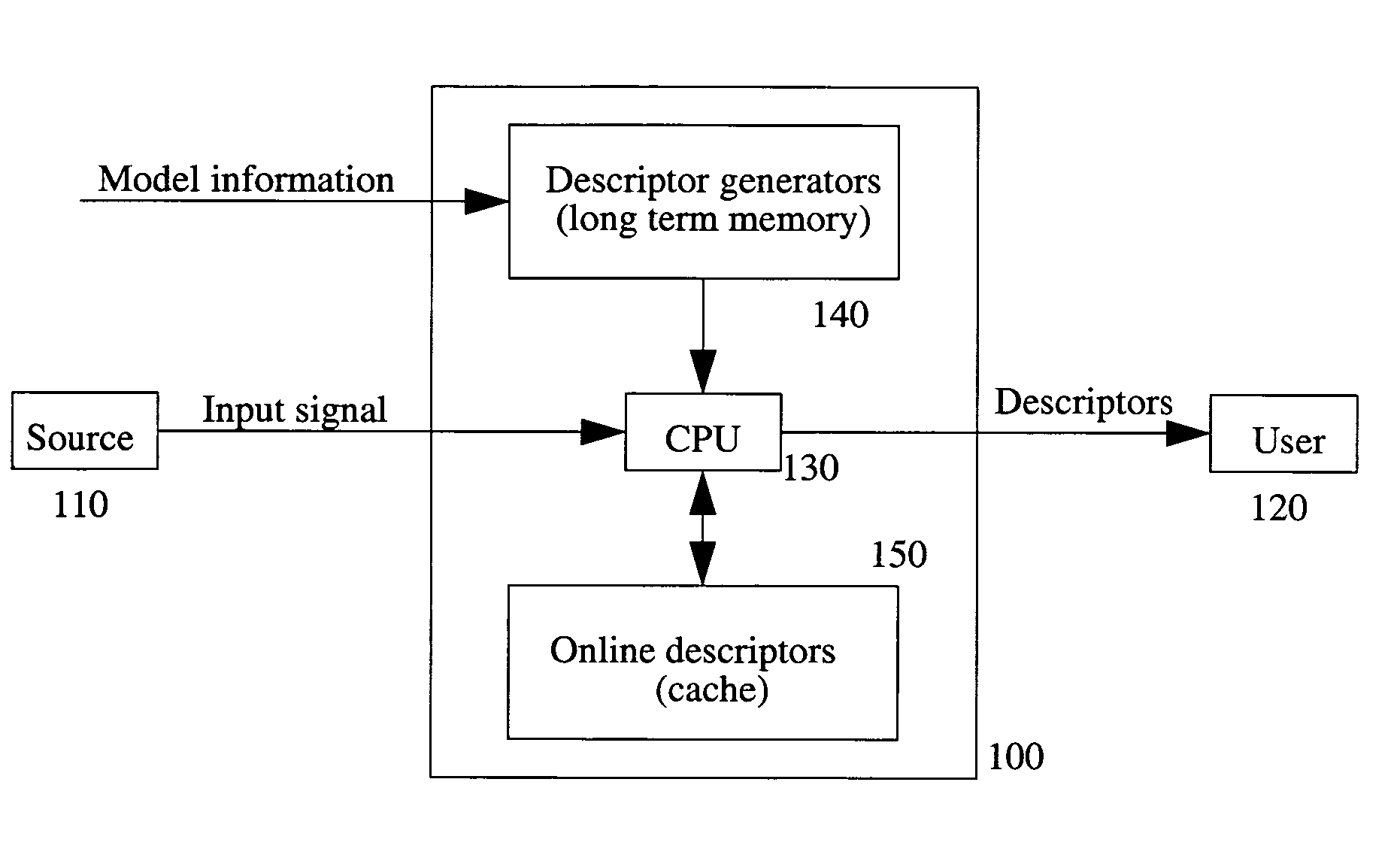
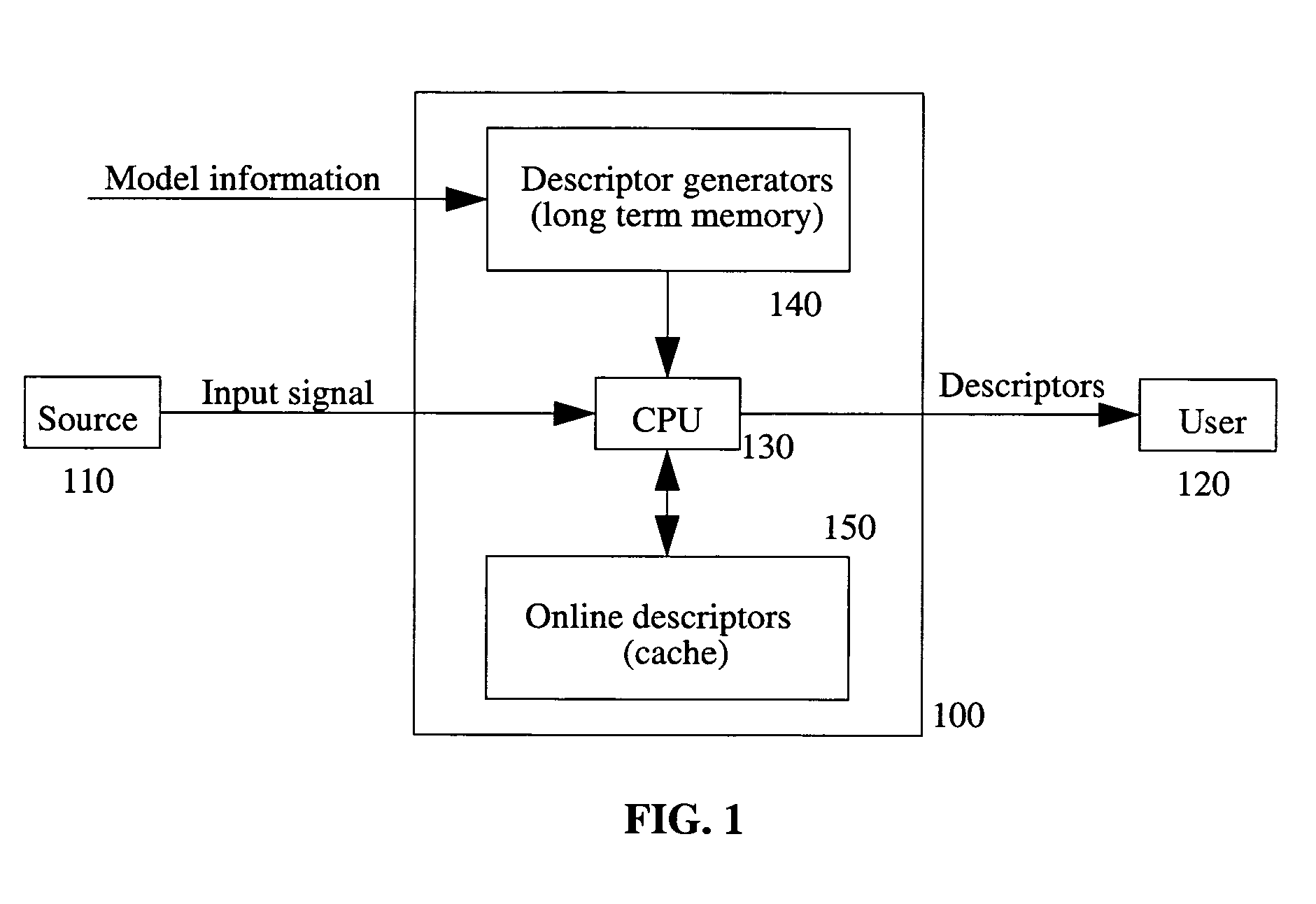
[0014]The main objective of this invention is to recognize models and to accurately estimate the associated model parameters in a computationally efficient way. More specifically, another related objective is to extract image features such as edges, corner points and junction points, and to accurately estimate various associated parameters such as location, orientation, and intensity values.

Problems solved by technology

While this approach is computationally efficient, it is known to lead to inaccurate estimates of important parameters such as the location of edges and the width of lines [17, 31].
A disadvantage of many existing optimization methods is their high computational requirements.
Another related disadvantage of most existing optimization methods is that intermediate results are typically not stored; hence, calculations performed for one signal block can not be reutilized to aid the processing of another signal block or to search for multiple model instances.
A critical and computationally difficult aspect of this “compositional” approach is to identify the groups of parts that must be composed together.
A major well-known disadvantage of these methods is that the boundaries of homogeneous regions do not always correspond to the boundaries of the entities to be recognized.
In addition, some portions of the signal may contain information about multiple parts so that a segmentation into non-overlapping regions, each assigned to a different part, may cause a loss of performance.
Hence, a limitation of matching pursuit is that the interference between components is neglected because components are recognized independently of each other.

Method used


Image

  • Hierarchical method and system for pattern recognition and edge detection
  • Hierarchical method and system for pattern recognition and edge detection
  • Hierarchical method and system for pattern recognition and edge detection

Examples


Embodiment Construction

Notation and Terminology

[0043]1. I: the input signal received by the signal processing system. The value of the signal at a “point” (or “site”) p is I(p). In some embodiments, I is an image and p=(x,y).[0044]2. U: the set of points, or domain on which the signal is defined, or a subset of it.[0045]3. V: the signal codomain, i.e., the set of values the signal can take on, e.g. V=R.[0046]4. VU: set of signals with support U.[0047]5. Descriptor: a piece of recordable data; it may comprise an estimated model parameter; or, it may be part of the output of a processing or filtering operation performed on the signal.[0048]6. Estimator: means for estimating a model parameter or a pattern. An incremental estimator in one that requires an initialization and produces an updated estimate. An autonomous estimator does not require initialization or provides one internally. An estimator can be either iterative or direct (i.e., non-iterative). An alternating estimator comprises a stage where parame...


PUM


Abstract

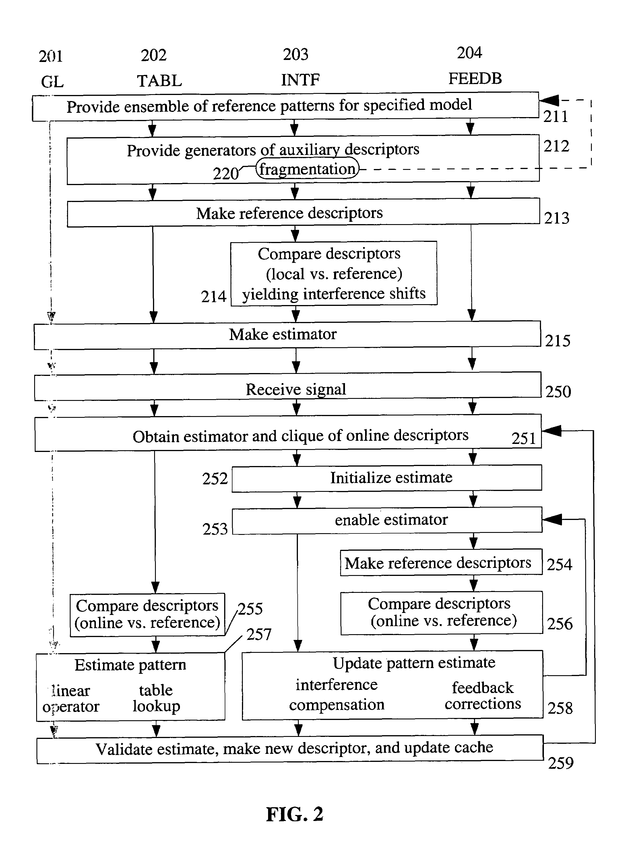
A method and a system for pattern recognition utilizes an ensemble of reference patterns to represent the possible instances of the models to be recognized; constructs a hierarchy of estimators to simplify and enhance the recognition of the models of interest; approximates complex reference patterns with linear compositions of simpler patterns; fragments complex patterns into local patterns so that interference between the local patterns is sufficiently small for linearization methods to be applicable; constructs estimators during an offline stage to offload calculations from the online signal processing stage; designs model estimators based on optimization principles to enhance performance and to provide performance metrics for the estimated model instances; generates a hierarchy of reference descriptors during the offline stage, which are used for the design and construction of the model estimators. Specific examples are provided for the recognition of image features such as edges and junctions.

Description

REFERENCE TO RELATED APPLICATIONS[0001]This application claims the benefit of U.S. Provisional Patent Application 60 / 584,049, filed Jun. 30, 2004, entitled “System and method to generate picture notes”; and U.S. Provisional Patent Application 60 / 675,887, filed Apr. 29, 2005, entitled “System and method for model recognition and feature extraction”, both by the same inventor.FIELD OF THE INVENTION[0002]This invention relates to the fields of signal processing, image processing, pattern recognition, and machine vision. More specifically, this invention relates to methods and systems for recognizing patterns and for extracting features including edges, corners, junctions, salient points, etc.BACKGROUND OF THE INVENTION[0003]In this disclosure, the term “pattern recognition” refers to the detection, estimation and classification of entities useful for performing a task. These entities may include high-level task-dependent objects such as roads, cars and faces; generic low-level features...

Claims


Application Information

Patent Timeline
Patent Type & Authority Patents(United States)
IPC IPC(8): G06K9/36G06V10/764
CPCG06K9/6206G06K9/6282G06T7/0083G06T2207/20164G06T2207/20016G06T7/12G06V10/754G06V10/764G06F18/24323
Inventor CASADEI, STEFANO
Owner CASADEI STEFANO
Learn More