Packaging container with clamping base

a packaging container and clamping technology, applied in the direction of container/bottle construction, rigid containers, apparel, etc., can solve the problems of clamping force, partial deformation of flexible ribs, and as great clamping for

Active Publication Date: 2010-06-22
ROESLER PETER
View PDF16 Cites 10 Cited by
  • Summary
  • Abstract
  • Description
  • Claims
  • Application Information

AI Technical Summary

Benefits of technology

[0014]In comparison with the prior art the given technical teaching results in the advantage that, only by means of the cap if it is attached to the base, the clamping force of the clamping holder is increased considerably.
[0016]This results in the advantage that, if the cap is removed, an object to be held can be easily inserted in the clamping reception being still open. Therefore, minor insertion forces are required only to insert this tool or the object in the clamping reception of the clamping holder being still open. Conditioned by high insertion forces being necessary to be applied injuries of the hand resulting from a sharp-edged tool are avoided.
[0019]This results in the considerable advantage that very heavy objects are also held safely in the clamping reception of the clamping holder. For example, such heavy objects are drills, milling cutters, and other tools, and / or instruments made of heavy metal having a high density which require to be protected against damages in a particular way and also if the packaging falls down.

Problems solved by technology

Since the ribs are made of a flexible material this results in a flexible clamping reception in case that the object to be held is inserted in the clamping reception which results in a partial deformation of these flexible ribs.
A disadvantage of this known clamping reception is that when the object to be held is inserted, the clamping force is as great as the clamping force in accordance with holding the object in the clamping reception.
A first disadvantage is that it is difficult to equip such packaging container, because the object to be held must be inserted in the clamping reception by overcoming the clamping force (with partial considerable force to be applied by the hand) of said clamping reception.
If the object is a sharp-edged tool or the like this will result in injuries of the hand due to the insertion force or holding force necessary to operate the tool.
A further disadvantage is that the clamping force can in no way be increased if the object is held in the clamping reception.

Method used


Image

  • Packaging container with clamping base
  • Packaging container with clamping base
  • Packaging container with clamping base

Examples


Embodiment Construction

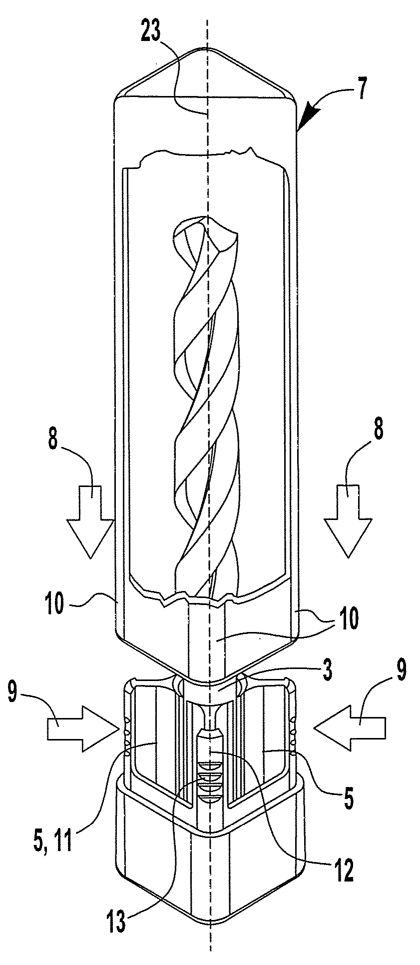
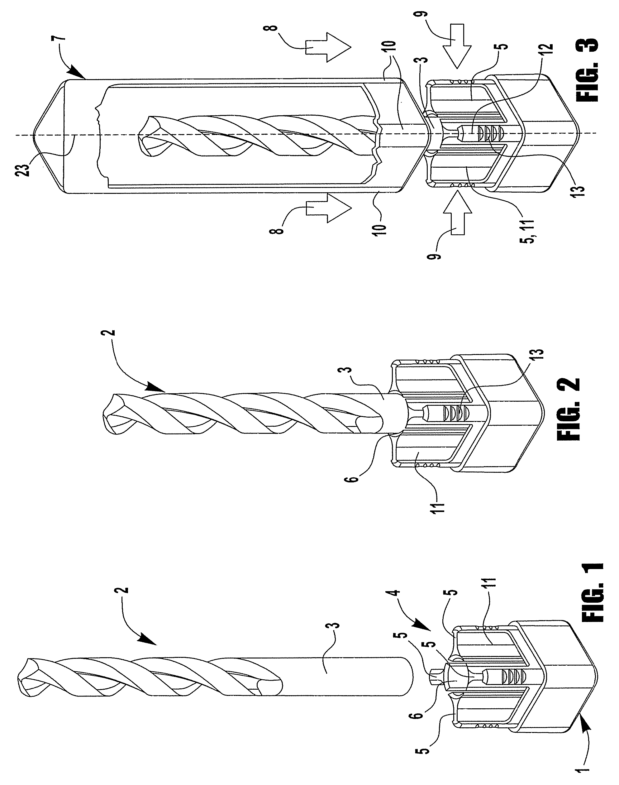
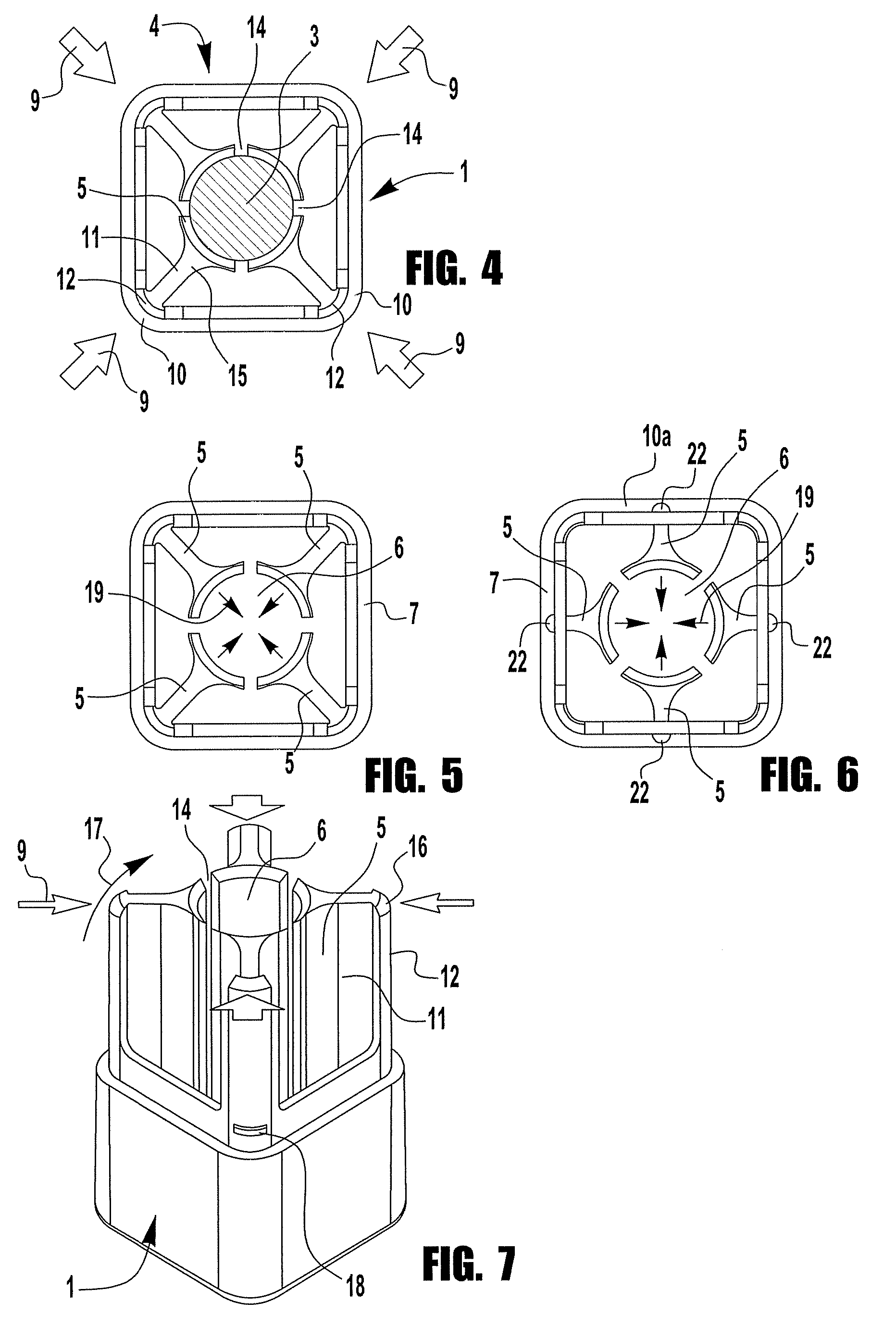
[0052]FIG. 1 shows a base 1 having a nearly quadratic cross-section developed preferably of a plastic material. Base 1 forms a clamping holder 4 which is formed of four clamping jaws 5 which are separated from each other elastically by longitudinal slots 14 extending in axial direction. In this way clamping jaws 5 may move in direction of arrow 17 (see FIG. 7) inwardly in direction of a central clamping reception 6 to clamp a tool 2 to be inserted there in the area of its shaft 3.

[0053]It is important that, with no cap attached, clamping reception 6 develops a greater diameter in comparison with the same diameter if a cap has been attached.

[0054]Therefore, in the position shown in FIG. 1 shaft 3 may be inserted in clamping reception 6 with the help of minor insertion force applied and is held there slightly only. This can be seen in FIG. 2.

[0055]However, if a protective cap 7 is attached to base 1 in direction of arrow 8 the areas of the edges 10 of the protective cap abut form-lock...


PUM


Abstract

A packaging container with a clamping base and an attachable protective cap serves for a unilateral, clamping or holding of a tool, an instrument, or another longitudinal object, where the clamping base comprises a clamping holder with a plurality of springy clamping jaws fastened on one side which define a nearly centric, central clamping reception, in which clamping reception the tool is inserted and held clampingly.In order to achieve that the insertion force to be applied is low when the packaging container is equipped, however, a high clamping force is given with the protective cap attached. The protective cap abuts against the outside circumference of the clamping jaws when it is attached to the clamping base and prestresses said clamping jaws in direction of the clamping reception.

Description

CLAIM OF PRIORITY[0001]This invention claims the benefit of German Patent Application Serial No. 10 2005 060 439.0, filed on Dec. 17, 2005.FIELD OF THE INVENTION[0002]The invention refers to a packaging container with a clamping base, and particularly a packaging container having a clamping holder with at least one elastic clamping jaw.BACKGROUND OF THE INVENTION[0003]Such packaging container with a clamping base has become known as such that a cap can be slid on a base. By this the cap covers the object to be protected, for example a tool, an instrument, or any other object, which object is received by the base of the packaging container.[0004]The known clamping base is developed as such that a clamping reception is formed in the area of the base by ribs arranged at the circumference uniformly distributed, which ribs are fixed at the internal surfaces of the base. At their corresponding ends the ribs project radially inwardly and as such they form a clamping reception. Since the ri...

Claims


Application Information

Patent Timeline
Patent Type & Authority Patents(United States)
IPC IPC(8): B65D85/28
CPCB25H3/003
Inventor ROESLER, PETER
Owner ROESLER PETER
Why Eureka
Try Eureka