
Solar light stick

a technology of solar energy and light sticks, which is applied in the direction of instruments, sensing by electromagnetic radiation, and power-in-place devices, etc., can solve the problems of inconvenient installation, inconvenient maintenance, and inconvenient use of incandescent or halogen light bulbs

Active Publication Date: 2010-06-22
EXHART ENVIRONMENTAL SYST
View PDF22 Cites 6 Cited by
  • Summary
  • Abstract
  • Description
  • Claims
  • Application Information

AI Technical Summary

Benefits of technology

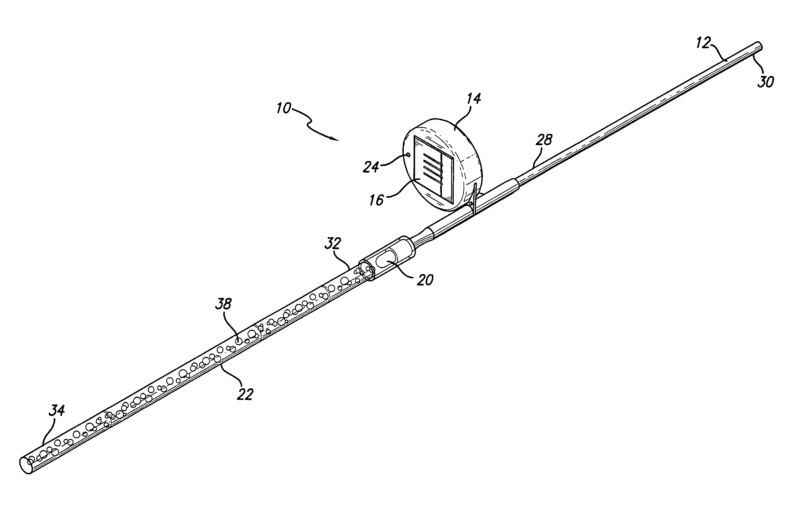
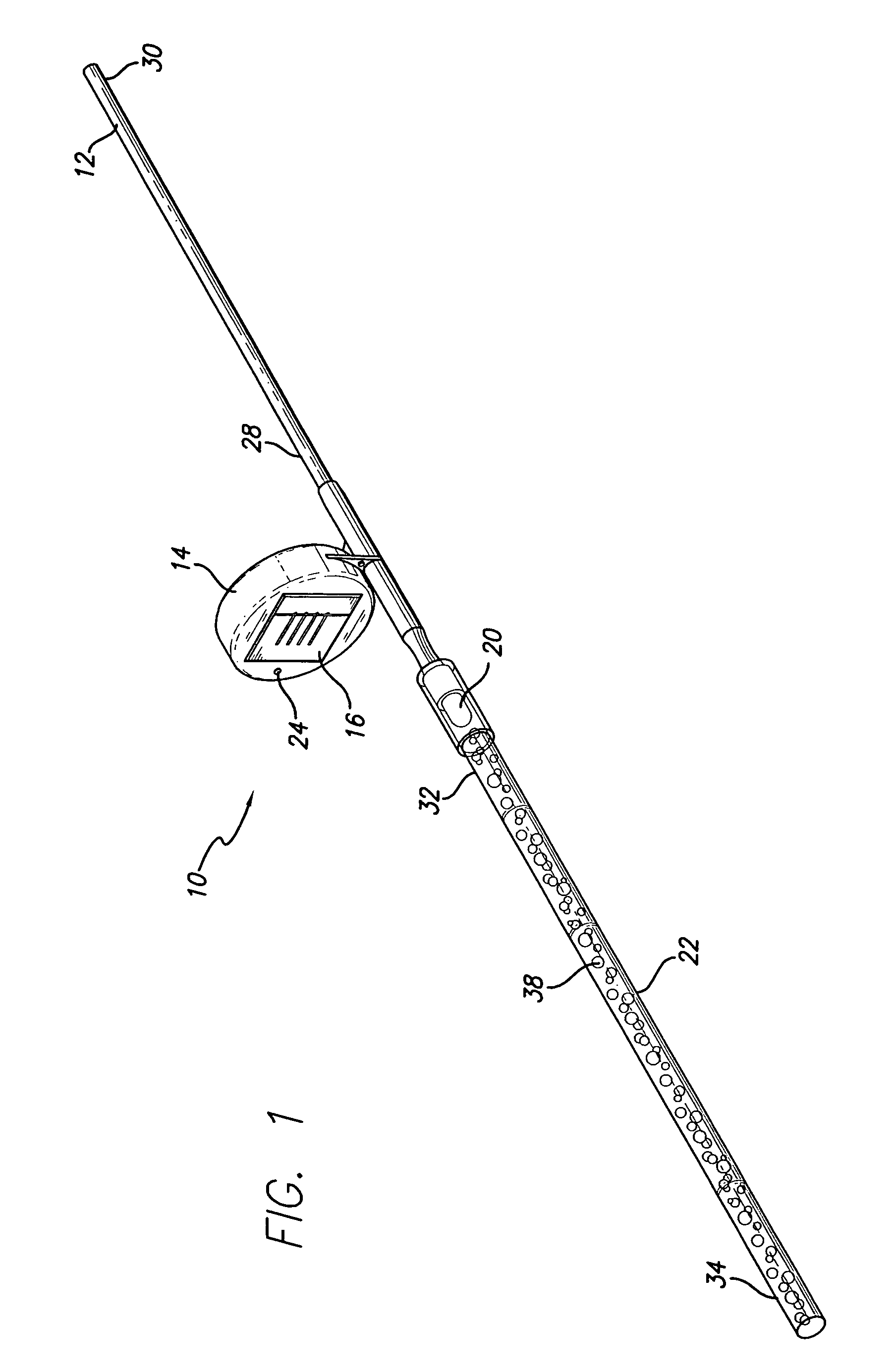
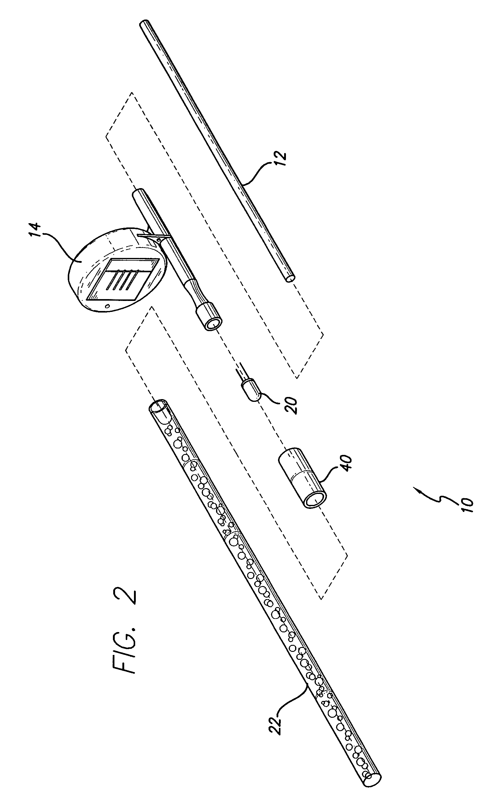
[0005]The LED is positioned to provide light to the interior of the wand. As such, the LED may be located within a recess in the wand. Voids, such as interior bubbles, suspended objects, or surface irregularities may help to disperse light from the LED in a direction external to the wand.

Problems solved by technology

As such the devices are sometimes used to mark a path that is otherwise difficult to discern in low light conditions.
However, these existing devices often require connection to an AC power source, intricate wiring between ornaments, expensive components, or energy inefficient incandescent or halogen light bulbs.

Method used


Image

  • Solar light stick
  • Solar light stick
  • Solar light stick

Examples


Embodiment Construction

[0010]The detailed description set forth below in connection with the appended drawings is intended as a description of presently-preferred embodiments of the invention and is not intended to represent the only forms in which the present invention may be constructed or utilized. The description sets forth the functions and the sequence of steps for constructing and operating the invention in connection with the illustrated embodiments. However, it is to be understood that the same or equivalent functions and sequences may be accomplished by different embodiments that are also intended to be encompassed within the spirit and scope of the invention.

[0011]Referring to the figures, the present invention is directed to a solar light stick 10 for use as a lawn or garden novelty. The solar light stick 10 has a support member 12, a housing 14, a solar panel 16, a rechargeable battery 18, an LED 20, a wand 22, an ambient light sensor 24, and an on-off switch 26.

[0012]The support member 12 ha...


PUM


Abstract

A solar light stick for use as a lawn or garden novelty. The solar light stick has a support member, a solar panel, a rechargeable battery, an LED, and a wand. The wand contains a light transmissive material that may be transparent or translucent. The solar panel charges the rechargeable battery which, in turn, provides power to the LED. The LED is positioned to provide light to the interior of the wand. As such, the LED may be located within a recess in the wand. Voids, such as interior bubbles, suspended objects, or surface irregularities may help to disperse light from the LED in a direction external to the wand.

Description

TECHNICAL FIELD[0001]This invention relates to solar powered, lighted lawn ornaments.BACKGROUND ART[0002]People are often interested in providing decoration to their lawns, gardens, driveways, and sidewalks, and there are many existing devices directed toward this use. One such device is the driveway or walkway light. These small lights provide illumination and decoration and, as the description suggests, are generally placed alongside driveways or walkways. As such the devices are sometimes used to mark a path that is otherwise difficult to discern in low light conditions. However, these existing devices often require connection to an AC power source, intricate wiring between ornaments, expensive components, or energy inefficient incandescent or halogen light bulbs. Furthermore, they are often available in just one color of light: white.[0003]There is therefore a need for a lighted lawn ornament that is simple in construction yet durable. There is further a need that the ornament b...

Claims


Application Information

Patent Timeline
Patent Type & Authority Patents(United States)
IPC IPC(8): G06K7/10
CPCF21S9/035F21V23/0442F21Y2101/02F21W2131/109F21W2121/00F21Y2115/10Y02B20/72
Inventor WEISER, ISAAC
Owner EXHART ENVIRONMENTAL SYST
Learn More