
Transflective color-balanced liquid crystal display

a liquid crystal display and color balance technology, applied in non-linear optics, instruments, optics, etc., can solve the problem of difficult to achieve high chromaticity, and achieve the effect of improving the chromaticity or color quality of the transflective-type liquid crystal display

Active Publication Date: 2010-06-22
AU OPTRONICS CORP
View PDF19 Cites 2 Cited by
  • Summary
  • Abstract
  • Description
  • Claims
  • Application Information

AI Technical Summary

Benefits of technology

"The present invention provides a method and a pixel structure for improving the color quality of a transflective liquid crystal display. The method involves sectioning the pixels into sub-pixels, each associated with a different color for viewing. The sub-pixels have a transmission area and a reflection area, and a color filter covering both areas. The method also includes filtering light incident on the sub-pixels based on their color to provide the desired color quality. The pixel structure includes a plurality of sub-pixels in each pixel, with at least one of the sub-pixels being associated with a different color for viewing. The display has a front side for viewing and an opposing backside for light transmission. The invention provides a better viewing experience for the viewer and improves the overall color quality of the display."

Problems solved by technology

Due to the simplicity in the pixel structure of the conventional transflective LCD panel, high chromaticity is difficult to achieve.

Method used


Image

  • Transflective color-balanced liquid crystal display
  • Transflective color-balanced liquid crystal display
  • Transflective color-balanced liquid crystal display

Examples


Embodiment Construction

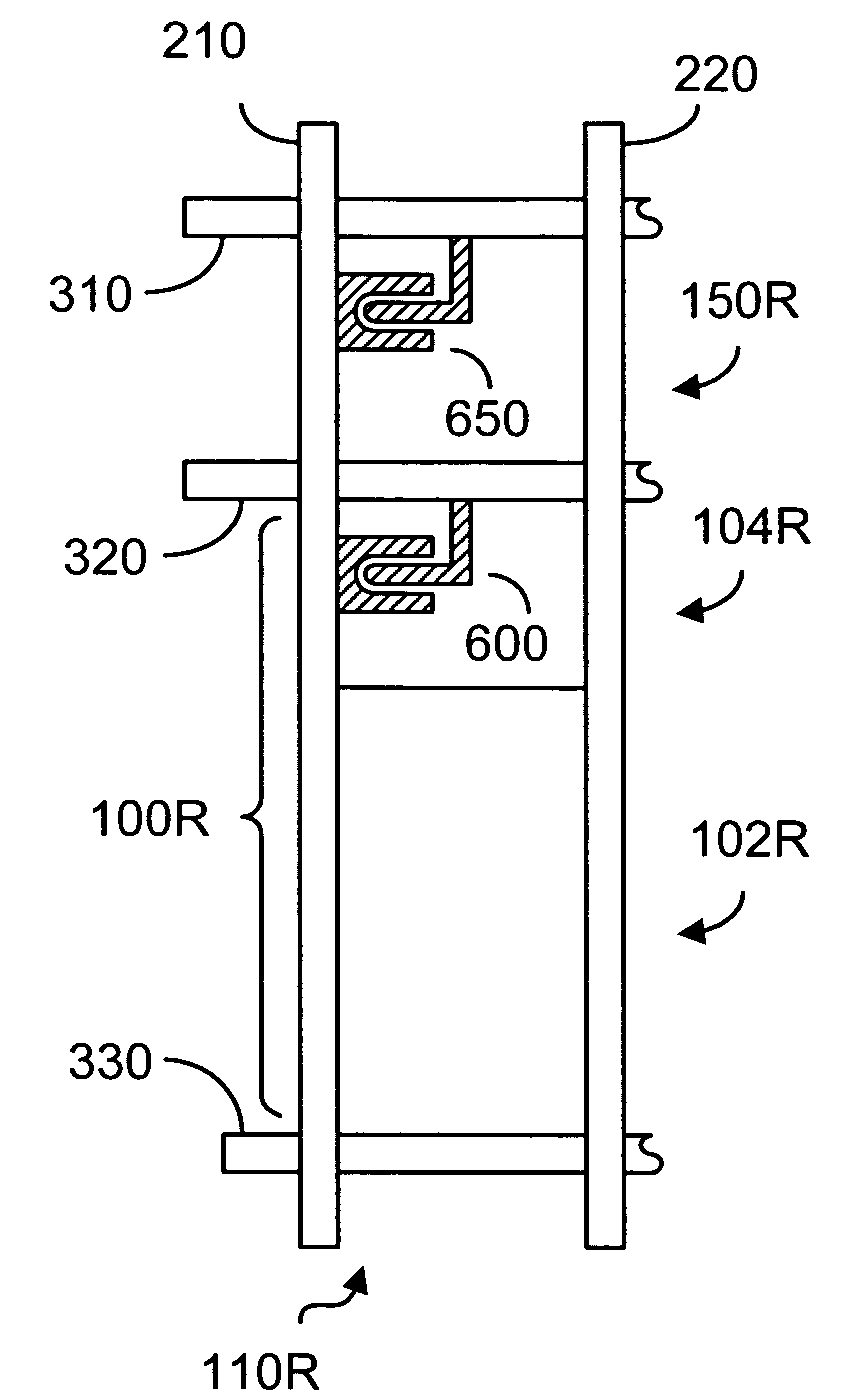
[0071]FIG. 4a is a schematic representation showing a plane view of a general structure of a pixel in an LCD display, according to one embodiment of the present invention. In FIG. 4a, the pixel 10 is a typical color picture element capable of showing at least three different color components in red (R), green (G) and blue (B). As shown in FIG. 4, the pixel 10 comprises three sub-pixel segments 110R, 110G and 110B for producing, respectively, the red component, green component and blue component in a color LCD display. The sub-pixel segment 110R comprises a color sub-pixel SR and an auxiliary sub-pixel AR associated with the color sub-pixel SR. Likewise, the sub-pixel segment 110G comprises a color sub-pixel SG and an auxiliary sub-pixel AG associated with the color sub-pixel SG, and the sub-pixel segment 110B comprises a color sub-pixel SB and an auxiliary sub-pixel AB associated with the color sub-pixel SB. The areas of the color sub-pixels SR, SG, SB are denoted by 100R, 100G, 100...


PUM

PropertyMeasurementUnit
areaaaaaaaaaaa
coloraaaaaaaaaa
transmissionaaaaaaaaaa

Abstract

In a transflective liquid crystal display comprising a plurality of pixels, each is divided into three color sub-pixels in red, green and blue. Each of the color sub-pixels is further divided into a main sub-pixel and an auxiliary sub-pixel. The main sub-pixel comprises a transflective area and a reflective area. The auxiliary sub-pixel can be entirely transmissive, reflective or partially transmissive and reflective. The liquid crystal display further comprises a plurality of first gate lines for electrically controlling the main sub-pixels and a plurality of second gate lines for electrically controlling the auxiliary sub-pixels. The auxiliary sub-pixels may have a color filter for partially filtering light encountering the auxiliary sub-pixels according to the color of the color sub-pixels.

Description

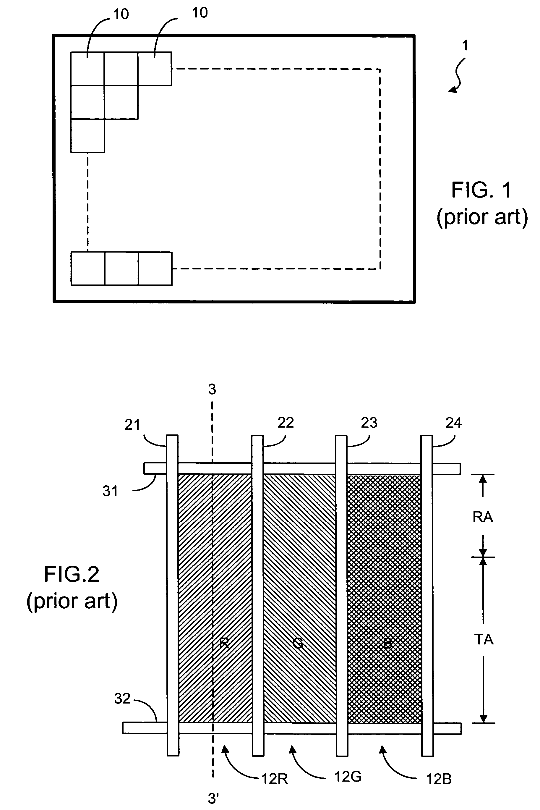
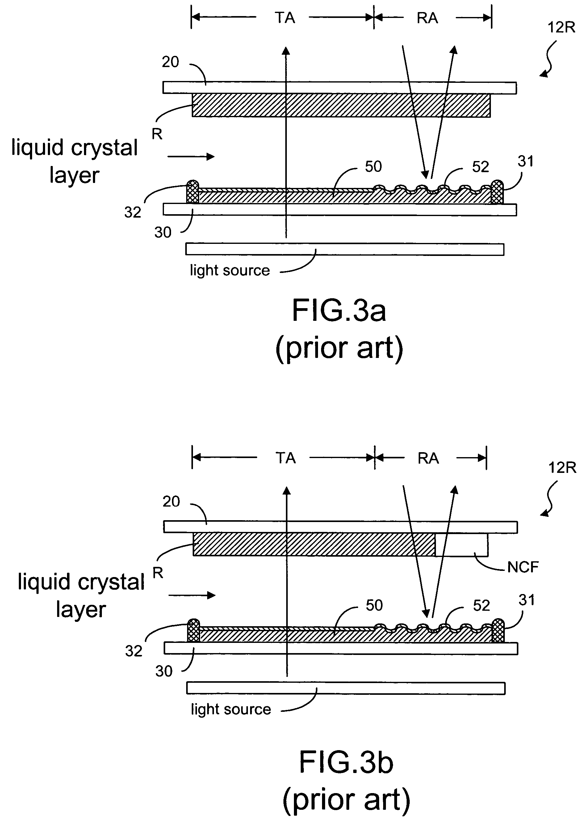
FIELD OF THE INVENTION[0001]The present invention relates generally to a liquid crystal display panel and, more particularly, to a transflective-type liquid crystal display panel.BACKGROUND OF THE INVENTION[0002]Due to the characteristics of thin profile and low power consumption, liquid crystal displays (LCDs) are widely used in electronic products, such as portable personal computers, digital cameras, projectors, and the like. Generally, LCD panels are classified into transmissive, reflective, and transflective types. A transmissive LCD panel uses a back-light module as its light source. A reflective LCD panel uses ambient light as its light source. A transflective LCD panel makes use of both the back-light source and ambient light.[0003]As known in the art, a color LCD panel 1 has a two-dimensional array of pixels 10, as shown in FIG. 1. Each of the pixels comprises a plurality of sub-pixels, usually in three primary colors of red (R), green (G) and blue (B). These RGB color comp...

Claims


Application Information

Patent Timeline
Patent Type & Authority Patents(United States)
IPC IPC(8): G02F1/1335G02F1/1343
CPCG02F1/133514G02F1/133555G02F2201/52G02F2001/134345G02F1/134345
Inventor HU, CHIH-JENCHANG, CHIH-MING
Owner AU OPTRONICS CORP
Learn More