

Flash-spun sheet material
a technology of plexifilamentary sheets and flashspun sheets, which is applied in the direction of filtration separation, separation processes, instruments, etc., can solve the problems of not being durable enough for dirty job applications, too expensive or uncomfortable for medical garment use, and not being entirely reliable in predicting the comfort of apparel sheet materials under actual dynamic workplace conditions
- Summary
- Abstract
- Description
- Claims
- Application Information
AI Technical Summary
Problems solved by technology
Method used
Image

Examples
examples
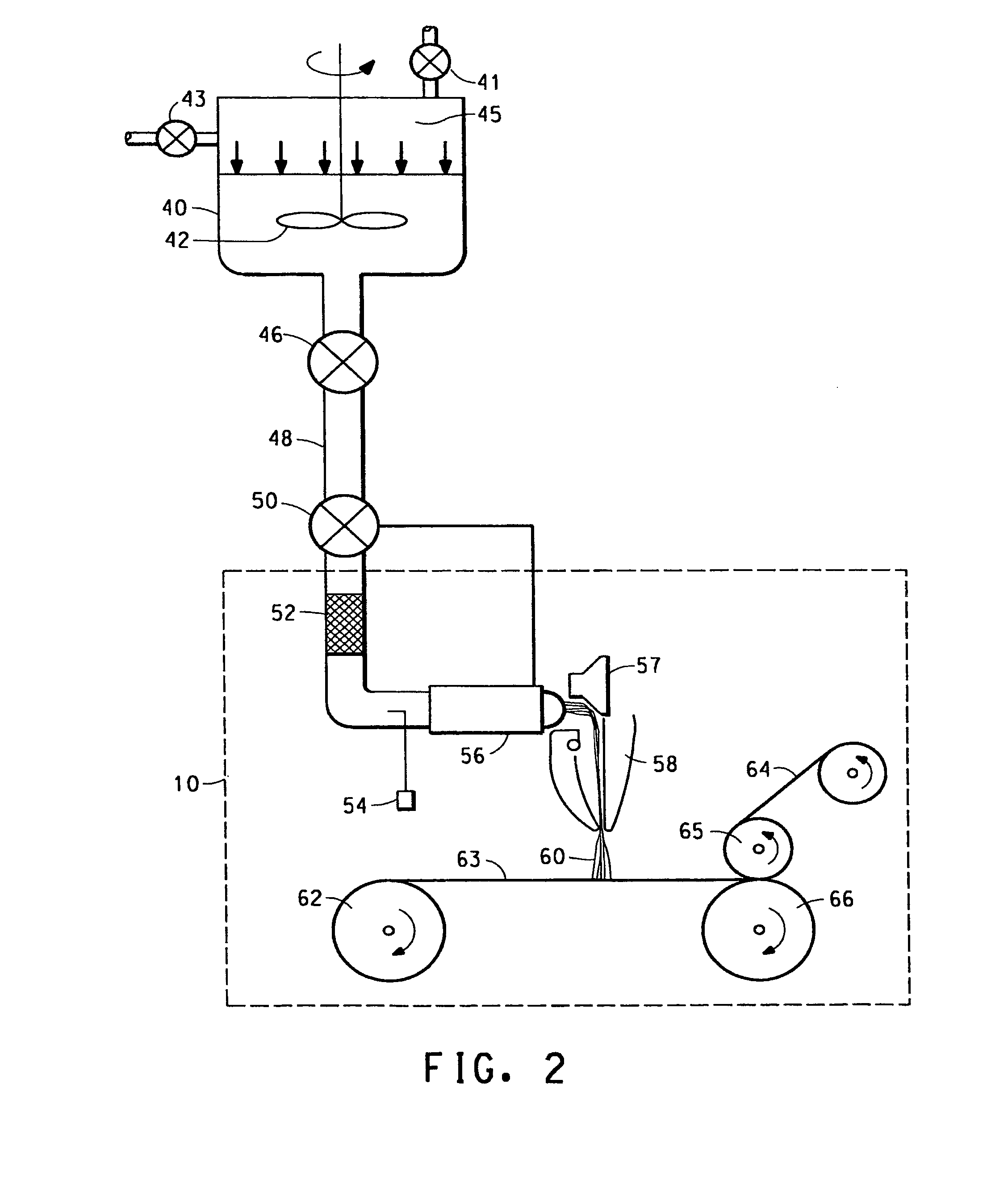
[0078]The spin fluids used in Examples 1-27 were prepared batch-wise in the 12 gallon autoclave described above with regard to FIG. 2. The spin fluids were prepared and flash-spun according to the process described above with regard to FIG. 2. The polymer concentrations reported in the examples were calculated as the weight percent of polymer based on the total spin fluid weight, where the total spin fluid weight includes the weight of polymer and spin agent.
[0079]Spin pack dimensions were as follows unless indicated otherwise: The orifice at the entrance end of the letdown chamber had a length of 0.064 cm and a diameter of 0.095 cm; the spin orifice at the exit end of the letdown chamber had a length of 0.064 cm and a diameter of 0.087 cm (L / D=0.74); the spin tunnel located immediately downstream of the spin orifice had a length of 0.84 cm, an entrance diameter of 0.46 cm, and an exit diameter of 0.61 cm. In the tables in the examples below, a spin orifice indicated as “std” is the...
examples 16-19
Filtration Properties
Whole Surface Bonded Sheets
[0094]In Examples 16 through 19, filtration properties were measured on whole surface bonded sheets of the current invention. In Example 16, filtration properties were measured on the whole surface bonded sheet described in Example 3 (spinning temperature=211° C., polymer concentration=22 weight percent based on total spin fluid). In Example 17, the whole surface bonded sheet of Example 3 was electrostatically charged using the method described in Tsai et al. U.S. Pat. No. 5,401,446, which is assigned to the University of Tennessee, before filtration properties were measured. In Example 18, filtration properties were measured on the whole surface bonded sheet described in Example 4 (spinning temperature=214° C., polymer concentration=16 weight percent based on total spin fluid). In Example 19, the whole surface bonded sheet of Example 4 was charged using the method described in Tsai et al. U.S. Pat. No. 5,401,446 before filtration prop...
examples 20-26
Through-Air Bonded Sheets
[0097]In Examples 20 through 26, unbonded flash-spun polyethylene sheets of the invention produced over a range of different flash-spinning temperatures and polymer concentrations, as described above, were through-air bonded according to the process described above with regard to FIG. 4. During the through-air bonding process, the sheets of open scrim material were left on both sides of the plexifilamentary sheet sample. The through-air bonding was done on a perforated drum unit like that shown in FIG. 4, having a drum diameter of 1.4 meters and a perforated section width (vacuum width) of 0.5 meters. The unbonded sheets rotated about 300° around the perforated drum at a line speed of 15 m / min. The bonding air was heated to the temperatures shown in Table 5. The heated air was passed through the sheet at a rate of about 0.5 to 2 m / sec during the time it took the sheet to travel around the bonding drum. Spinning and bonding conditions for the sheets, and shee...
PUM
| Property | Measurement | Unit |
|---|---|---|
| temperature | aaaaa | aaaaa |
| temperature | aaaaa | aaaaa |
| temperature | aaaaa | aaaaa |
Abstract
Description
Claims
Application Information