Pump failure alarm device

a technology for alarm devices and pumps, applied in the direction of pump components, non-positive displacement fluid engines, instruments, etc., can solve the problems of large heat generation and ruined cpu

Inactive Publication Date: 2010-06-29
HONG FU JIN PRECISION IND (SHENZHEN) CO LTD +1
View PDF6 Cites 13 Cited by
  • Summary
  • Abstract
  • Description
  • Claims
  • Application Information

AI Technical Summary

Problems solved by technology

During operation of many contemporary electronic devices such as central processing units (CPUs), large amounts of heat are produced.
If either or both of the pumps run unstably or even cease running, heat generated from the CPU will not be dissipated on time and will ruin the CPU.

Method used


Image

  • Pump failure alarm device
  • Pump failure alarm device

Examples


Embodiment Construction

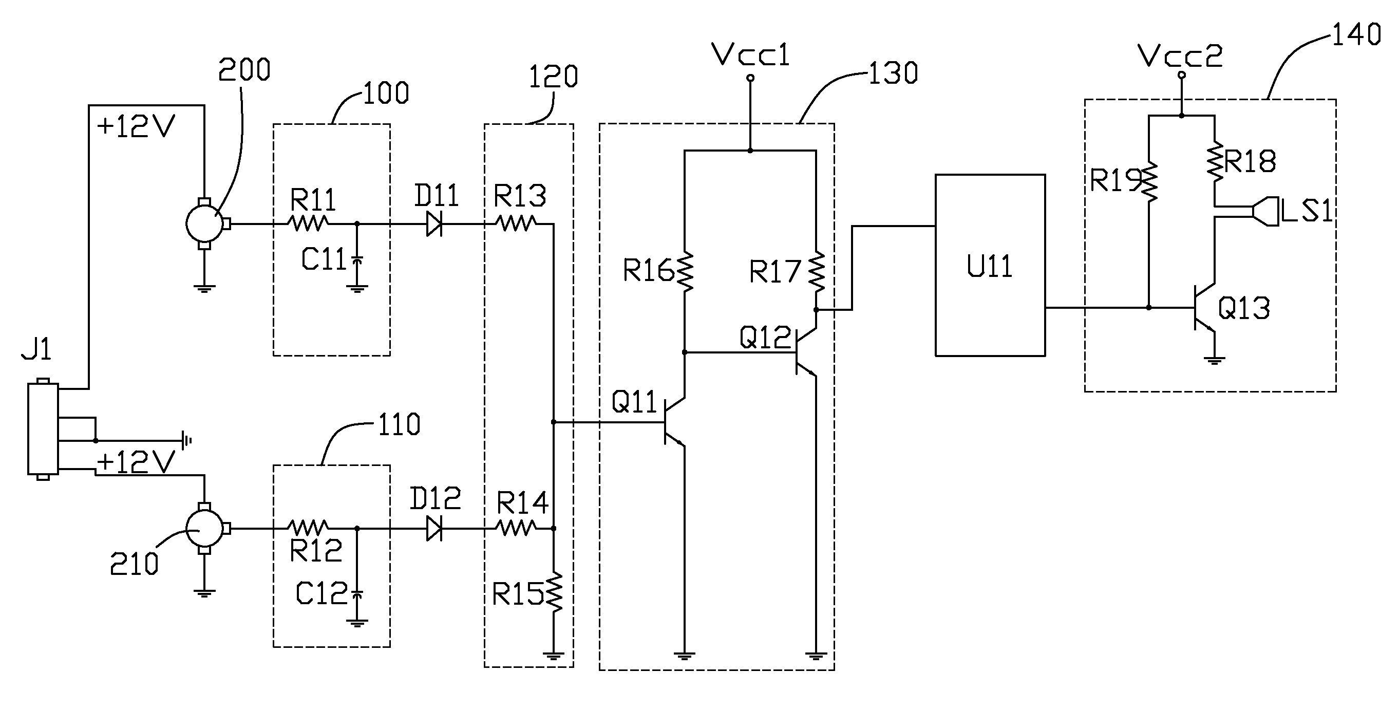
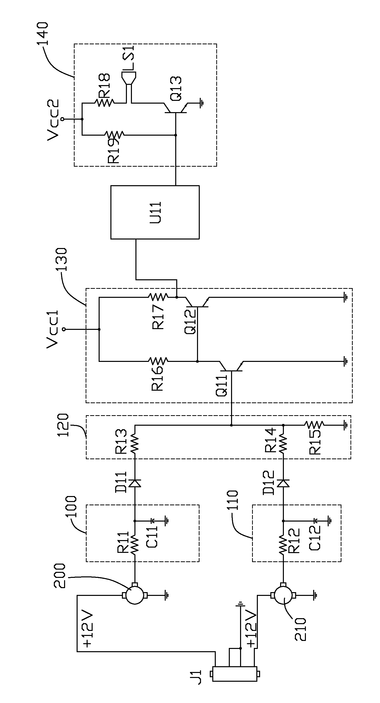
[0010]Referring to the drawing, an alarm device for pumps in accordance with an embodiment of the present invention includes two digital-analog converting circuits 100, 110, two diodes D11, D12, a voltage sampling circuit 120, a controlling circuit 130, an input-output (I / O) controller U11, and an alarm circuit 140.

[0011]In this embodiment, the digital-analog converting circuit 100 includes a resistor R11 and a capacitor C11. One terminal of the resistor R11 is coupled to a pump 200, the other terminal of the resistor R11 is coupled to one terminal of the capacitor C11, the other terminal of the capacitor C11 is coupled to ground. The digital-analog converting circuit 110 includes a resistor R12 and a capacitor C12. One terminal of the resistor R12 is coupled to a pump 210, the other terminal of the resistor R12 is coupled to one terminal of the capacitor C12, the other terminal of the capacitor C12 is coupled to ground. A node between the resistor R11 and the capacitor C11 is coupl...


PUM


Abstract

A pump failure alarm device includes two digital-analog converting circuits (100, 110), a voltage sampling circuit (120), a controlling circuit (130), an I / O controller (U11), and an alarm circuit (140). The digital-analog converting circuits receive digital pulse signals from two pumps (200, 210), and respectively output a DC voltage signal at an output terminal when the pumps run normally. The voltage sampling circuit with two input terminals respectively coupled to the output terminals of the two digital-analog converting circuits, and outputs a first voltage signal when the two pumps run normally and outputs a second voltage signal when either or both of the pumps stop running. The controlling circuit receives the voltage signals from the voltage sampling circuit, and outputs a first control signal when it receives the first voltage signal and outputs a second control signal when it receives the second voltage signal. The I / O controller receives the control signals from the controlling circuit, and outputs an alarm signal when it receives the second control signal. The alarm circuit receives the alarm signal from the I / O controller, and activates an alarm.

Description

CROSS-REFERENCES TO RELATED APPLICATION[0001]This application is related to a co-pending application entitled with “FAN FAILURE ALARM DEVICE”, filed on Sep. 20, 2007 with application Ser. No. 11 / 858,122, and assigned to the same assignee of the present invention.BACKGROUND[0002]1. Field of the Invention[0003]The present invention relates to alarm devices, and particularly to an alarm device for indicating a failure of pumps in a computer system.[0004]2. Description of Related Art[0005]Developments in today's highly information-intensive society have led to remarkable improvements in performances of electronic devices. During operation of many contemporary electronic devices such as central processing units (CPUs), large amounts of heat are produced. Typically, two pumps are used to facilitate removal of heat. One pump is used to pump water, the other pump is used to drain water. The pumps must be running stably, so as to prevent the device from becoming unstable or being damaged. If...

Claims


Application Information

Patent Timeline
Patent Type & Authority Patents(United States)
IPC IPC(8): G08B21/00
CPCF04D29/586F04D15/02
Inventor CHEN, YINGXIONG, JIN-LIANG
Owner HONG FU JIN PRECISION IND (SHENZHEN) CO LTD
Why Eureka
Try Eureka