Valved holding chamber for use with an aerosol medication delivery system

a technology of aerosol medication and holding chamber, which is applied in the direction of functional valve types, process and machine control, instruments, etc., can solve the problems of not optimizing the mixing of medication and air, medication may not be inhaled into the patient's lungs, and the devices described in these patents are relatively complicated

Inactive Publication Date: 2010-07-06
RIC INVESTMENTS LLC
View PDF23 Cites 31 Cited by
  • Summary
  • Abstract
  • Description
  • Claims
  • Application Information

AI Technical Summary

Benefits of technology

[0009]Accordingly, it is an object of the present invention to provide an aerosol delivery system that overcomes the shortcomings of conventional aerosol delivery systems. This object is achieved according to one embodiment of the present invention by providing an aerosol delivery system that includes a canister adapted to dispense a medicine, a canister holder adapted to couple to the canister, and a valved holding chamber that is adapted to be coupled to an end of the canister holder so that medicine or other fluid dispensed from the canister via the canister holder enters the valved holding chamber. The valved holding chamber includes a housing having a first end portion, a second end portion, and a chamber defined in the housing. A first chamber opening is defined in the first end portion and a second chamber opening is defined in the second end portion of the housing both of which provide access to the chamber. A mouthpiece is coupled to the first end portion of the housing, and a valve assembly is coupled to the housing, the mouthpiece, or both. The valve assembly is coupled to these elements such that fluid flow in a first direction from the housing to the mouthpiece passes through the valve assembly. More specifically, the valve assembly includes a conical flange having a first end coupled to the housing, the mouthpiece, or both such that the conical flange tapers in the first direction. A one-way valve element is disposed at the second end of the conical flange to allow fluid to flow from the chamber to the mouthpiece, i.e., in the first direction, but prevent fluid flow in an opposite direction. A valved holding chamber of such configuration provides improved medication / air mixing because the unobstructed flow of gas from the chamber into the valve assembly and the conical shape of the valve assembly provides a smooth transition, in terms of fluid flow, from the chamber to the one-way valve element.
[0010]A further embodiment of the present invention provides a simple and effective technique for preventing fluid flow back into the chamber, which is especially likely as the patient exhales into the mouthpiece, by providing an exhaust port in a conical collar portion of the mouthpiece and an exhaust valve element disposed over the exhaust port. The exhaust valve element is preferably selectively attachable to the exterior of the mouthpiece so that the exhaust valve element and the mouthpiece can be easily separated, cleaned, and reassembled.

Problems solved by technology

Although it is common for a patient to use the canister holder as a mouthpiece for receiving the aerosolized medication into their airway directly from the aerosol dispensing leg of the canister holder, this configuration may not optimize the mixing of the medication with the air because the aerosolized medication is injected directly into the airway.
Without adequate mixing of the drug with the air, the medication may not be inhaled into the patient's lungs where it is effective, but may form as droplets that are deposited in the patient's mouth and swallowed without the desired medicinal effect.
Furthermore, the devices described in these patents are relatively complicated, especially in the valves used to control the flow of the drug / air mixture and patient exhalation.
The more complicated the system, the more prone they are to failure or degradation in performance, for example due to clogging, and the more difficult it is to disassemble, clean, and reassemble the system correctly and quickly.

Method used


Image

  • Valved holding chamber for use with an aerosol medication delivery system
  • Valved holding chamber for use with an aerosol medication delivery system
  • Valved holding chamber for use with an aerosol medication delivery system

Examples


Embodiment Construction

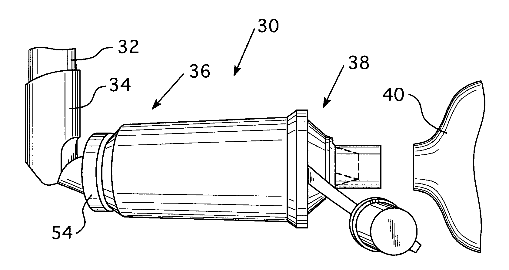
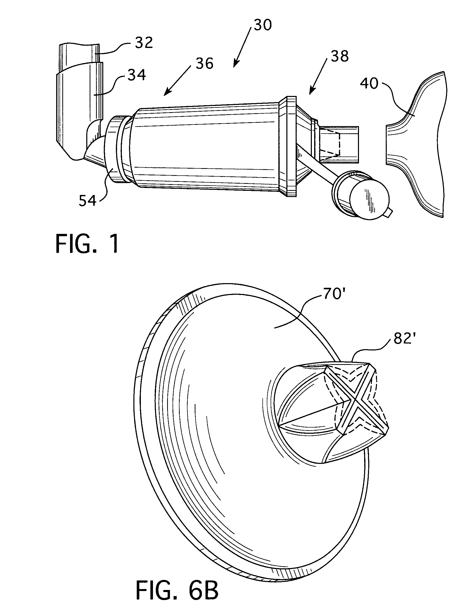
[0021]FIG. 1 is a side view of an exemplary embodiment of an aerosol medication delivery system 30 according to the principles of the present invention. Aerosol medication delivery system 30 includes a canister 32 adapted to dispense a medicine, a canister holder 34 that holds the canister, and a valved holding chamber 36 that attaches to the fluid dispensing end of the canister holder. The present invention contemplates that canister 32 and canister holder 34 are conventional devices. The unique features of the present invention are believed to reside in the valved holding chamber that selectively couples to an end of the canister holder. A mouthpiece assembly 38 provided at a first end of valved holding chamber 36 communicates with an airway of a patient (not shown), either directly, by having the patient place his or her lips on the mouthpiece, or indirectly, by attaching a mask 40 to the mouthpiece. Details of valved holding chamber 36 are discussed below the reference to FIGS. ...


PUM


Abstract

The present invention pertains to a valved holding chamber suitable for use in an aerosol medication delivery system. The valved holding chamber includes a housing and a mouthpiece coupled to the housing. A one-way valve assembly is coupled to the housing, the mouthpiece, or both so that fluid flows in a first direction from the housing to the mouthpiece passes through the valve assembly but does not pass back into the housing. The valve assembly includes a conical flange disposed such that the conical flange tapers in the first direction to smooth the fluid flow in the first direction toward the patient. In a further embodiment, the mouthpiece includes an exhaust port defined in a conical collar portion of the mouthpiece, and an exhaust valve element is disposed over the exhaust port to provide a one-way flow of fluid from within the mouthpiece to ambient atmosphere via the exhaust port.

Description

CROSS-REFERENCE TO RELATED APPLICATIONS[0001]This application claims priority under 35 U.S.C. §119(e) from provisional U.S. patent application No. 60 / 472,856 filed May 23, 2003 the contents of which are incorporated herein by reference.BACKGROUND OF THE INVENTION[0002]1. Field of the Invention[0003]The present invention pertains to an aerosol medication delivery system, and, in particular, to a valved holding chamber for use in an aerosol medication delivery system that maximizes delivery of the aerosol medication to a patient.[0004]2. Description of the Related Art[0005]It is well known to deliver a medication to a patient's respiratory system to treat a medical condition using an aerosol medication delivery system. For example, a patient suffering from an acute asthmatic attack may use an aerosol medication delivery system to deliver a bronchodilator, such as albuterol (salbutamol), in the form of a fine mist to the patient's respiratory system.[0006]A conventional aerosol medicat...

Claims


Application Information

Patent Timeline
Patent Type & Authority Patents(United States)
IPC IPC(8): A61M16/20A62B18/10A61M15/00
CPCA61M15/0086A61M15/0016A61M15/0018F16K15/144Y10T137/2544Y10T137/7842Y10T137/7882
Inventor LIEBERMAN, ERICVON HOLLEN, DIRK
Owner RIC INVESTMENTS LLC
Why Eureka
Try Eureka