Device for destroying subsea or floating objects

a technology for underwater objects and subsea, applied in underwater equipment, underwater torpedoes, weapons, etc., can solve the problems of mine explosion, difficult destruction of floating moored mines that have been cut, or mines drifting on the surface, and relatively difficult problems

Active Publication Date: 2010-07-13
ECA ROBOTICS
View PDF9 Cites 3 Cited by
  • Summary
  • Abstract
  • Description
  • Claims
  • Application Information

AI Technical Summary

Benefits of technology

[0016]Thus, the second part surrounded by the fairing can pivot, with the hydrodynamics of the device being maintained. The mobility characteristics of the craft are maintained, hence it is easier to control, quicker to bring into a firing position, more reliable in operation, and has a higher destruction success rate. Any projecting sensors on the second part disposed inside the fairing can pivot, provoking only a marginal or even zero modification to its water resistance.
[0024]In one embodiment of the invention, the fairing is fixed to the first part to improve the hydrodynamics in all phases of navigation and protect the second part from any debris likely to be encountered. The fairing can be fixed to the front of the first part. The fairing can be fixed roughly to the center of the first part. The fairing can take the form of a portion of a sphere or cylinder, or a combination of both connected to a cylindrical body of the first part.

Problems solved by technology

After having recovered the subsea craft on board a mine-sweeping surface vessel, the mine is destroyed by causing the charge to explode, the shockwave of which causes the mine to explode by its influence.
Now, modern sea-bed mines may no longer explode by influence and the destruction by gun of floating moored mines that have been cut or mines drifting on the surface can be difficult because of choppy sea and / or poor visibility.
This is also true for the moored mines that are to be destroyed directly, which is relatively difficult, particularly where there are underwater currents.
Furthermore, recovering the subsea craft takes time.
Conventional single-body craft do not allow for objects to be observed and then attacked from above, from below or from the side, unless they have a propulsive architecture that enables the craft to be directed.
This leads to the presence of a large number of propulsive units, which considerably increases the cost of the craft.
This is all the more true in the presence of sea currents, where such a craft will have great difficulty in maintaining its stability and holding its position.
However, the applicant has realized that the pivoting of the second part would risk modifying the hydrodynamic characteristics of the craft and, as a consequence, provoke an undesirable movement of the submersible craft relative to the subsea object.

Method used


Image

  • Device for destroying subsea or floating objects
  • Device for destroying subsea or floating objects
  • Device for destroying subsea or floating objects

Examples


Embodiment Construction

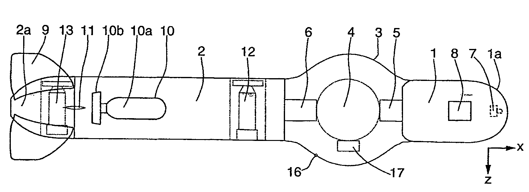
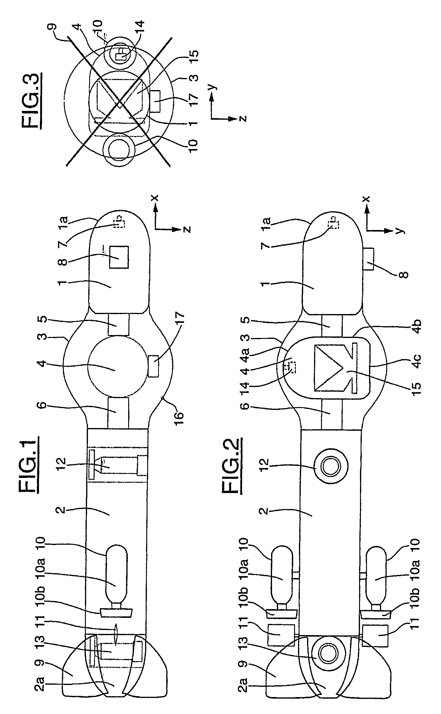
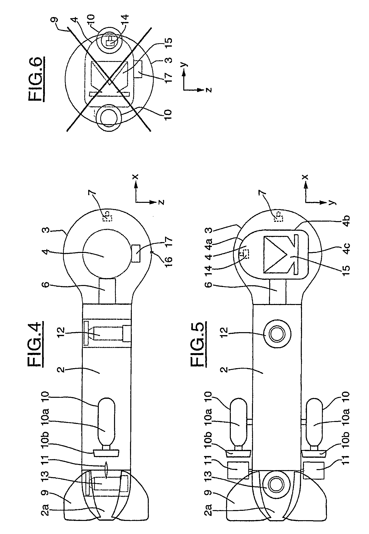
[0049]As can be seen in FIGS. 1 to 3, the subsea craft comprises a front body 1, of generally cylindrical shape, and having a front end 1a of generally hemispherical shape, a rear body 2, of generally cylindrical shape, and provided with a rear end 2a of truncated ogival shape, a fairing 3 disposed between the front body 1 and rear body 2, of generally spherical shape, truncated by two parallel planes equidistant from the center of said sphere and connected to the front body 1 and rear body 2 by connecting fillets of generally torroidal shape, and a pivoting part 4 disposed in the fairing 3 about a longitudinal axis X of the subsea craft, the lateral axis being denoted Y and the depths axis or vertical axis being denoted Z, according to the normal position of a craft in the water.

[0050]The pivoting part 4 is supported by the front body 1 and rear body 2 by trunions, respectively 5 and 6. One of the two trunions 5 or 6 is motorized, so that the rotation of the pivoting part 4 is cont...


PUM


Abstract

A device for destroying subsea objects comprising a first part 2 provided with propulsive units, a second part 4 which can pivot relative to the first part on an axis, so that the device can approach a subsea object from different directions, and a fairing 3 protecting the second part 4.

Description

BACKGROUND OF THE PRESENT INVENTION[0001]1. Field of Invention[0002]The present invention relates to the field of devices for destroying subsea objects likely to present a hazard for navigation, for example mines.[0003]2. Description of Related Arts[0004]Two main types of mines are known: sea-bed mines which rest on the sea bed, and moored mines which are held by a “mooring” rope to a kentledge. Sea-bed mines are destroyed by deploying an explosive charge called “warhead” in the immediate proximity of the subsea object and exploding it. This method entails marking the mine then bringing the warhead nearby and finally causing the explosion, unlike the dragging of mines that normally is based on magneto-acoustic and / or mechanical means to trigger the mines or cut their mooring rope.[0005]The known methods of destroying a sea-bed subsea mine comprise a step for detecting and / or identifying the mine and a step for destroying the mine using a large explosive charge, of the order of 50 to...

Claims


Application Information

Patent Timeline
Patent Type & Authority Patents(United States)
IPC IPC(8): B63G8/00
CPCB63G7/02B63C11/42F42B12/12F42B19/00F42B19/005
Inventor SCOURZIC, DANIELMEIRIER, ANDRE
Owner ECA ROBOTICS
Why Eureka
Try Eureka