System and method for isolating an individual radiation pattern of a given radiator in the presence of other radiators

a technology of radiators and radiation patterns, applied in the direction of antenna radiation diagrams, instruments, antennas, etc., can solve the problems of difficult to measure the near-field radiation pattern of the car with the antenna, art approaches to performing near-field scans, and inability to measure the far-field radiation pattern of an object the size of an automobile. , to achieve the effect of reducing the complexity of the scan apparatus

Active Publication Date: 2010-07-13
MICROWAVE INSTR TECH
View PDF3 Cites 8 Cited by
  • Summary
  • Abstract
  • Description
  • Claims
  • Application Information

AI Technical Summary

Benefits of technology

[0012]Accordingly, one advantage of the present invention is that it better enables determining the far-field radiation pattern of an antenna that is within a composite radiator.
[0013]Another advantage of the present invention is that it reduces the complexity of the scan apparatus required to do a near-field scan of a large composite radiator in which the antenna is not centered.
[0014]Yet another advantage of the present invention is that it obviates the need to modify an antenna measurement system to place the antenna at the crossing point of scan axes.
[0015]Additional advantages of the invention will be set forth in the description that follows, and in part will be apparent from the description, or may be learned by practice of the invention. The advantages of the invention will be realized and attained by the structure pointed out in the written description and claims hereof as well as the appended drawings
[0016]To achieve these and other advantages, the present invention involves a method for determining a far-field pattern of an antenna within a composite radiator. The method comprises performing a near-field scan of the composite radiator; computing a first plurality of coefficients corresponding to the near-field scan; computing a first far-field pattern corresponding to the first plurality of coefficients; computing a phase adjustment corresponding to a translation from a scan origin to a point within the antenna; computing a second far-field pattern corresponding to the first far-field pattern and the phase adjustment, the second far-field pattern having a second plurality of coefficients; reducing the second plurality of coefficients to a third plurality of coefficients, wherein a quantity of the third plurality of coefficients corresponds to a minimum sphere that is centered at the point within the antenna and substantially exclusively encompasses the antenna; and computing a third far-field pattern corresponding to the third plurality of coefficients.
[0017]In another aspect of the present invention, the aforementioned and other advantages are achieved by a system for determining a far-field radiation pattern of an antenna included within a composite radiator. The system comprises a scan probe; a two-axis position control system; and a host computer coupled to the two-axis position control system, the host computer having a computer readable medium encoded with a program for measuring a near-field radiating pattern according to a spherical scan at an angular sample spacing; computing a first plurality of coefficients corresponding to the near-field pattern; computing a phase adjustment corresponding to a translation from an origin corresponding to the spherical scan to a point within the antenna; computing a second plurality of coefficients, wherein the second plurality of coefficients corresponds to a far field pattern and the phase adjustment; reducing the second plurality of coefficients according to a minimum sphere substantially exclusively encompassing the antenna; computing a third plurality of coefficients corresponding to the reduced second plurality of coefficients; and computing the far-field radiation pattern based on the third plurality of coefficients.

Problems solved by technology

It is impractical to measure the far-field radiation pattern for an object the size of an automobile.
However, there are problems in related art approaches to performing the near-field scan.
It is extremely difficult to measure the near-field radiation pattern of the car with the antenna, and to filter out the effects of the car on the antenna's far-field radiation pattern computed from the near-field scan.
Second, it is extremely difficult to determine the far-field radiation of the pattern without secondary radiative effects of the automobile itself.
Although the above discussion uses an automobile as an example, the same issues arise with other vehicles, such as airplanes and boats, as well as other types of antenna applications, such as satellite-mounted antennas, phased-array antennas, etc.

Method used


Image

  • System and method for isolating an individual radiation pattern of a given radiator in the presence of other radiators
  • System and method for isolating an individual radiation pattern of a given radiator in the presence of other radiators
  • System and method for isolating an individual radiation pattern of a given radiator in the presence of other radiators

Examples


Embodiment Construction

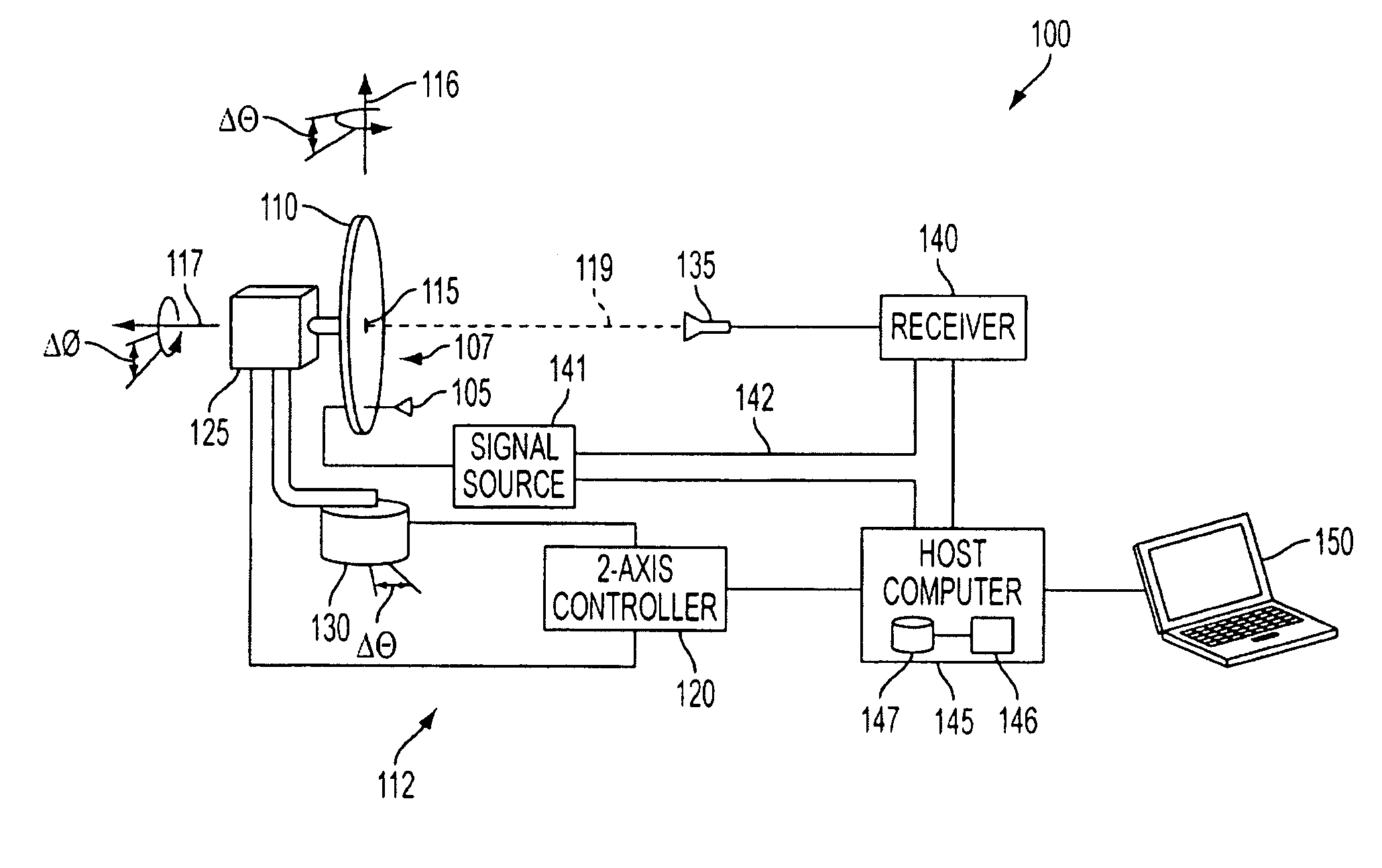
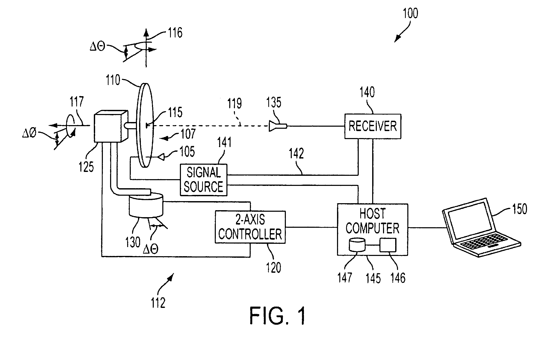
[0028]FIG. 1 illustrates an exemplary system 100 for determining an antenna far-field radiation pattern according to the present invention. System 100 includes a composite radiator 107, which includes an antenna 105 that is mounted to a ground plane 110. Antenna 105 may be connected to a signal source 141. Ground plane 110 may include the roof of a car, part of the fuselage of an airplane, structure of a phased antenna array, etc. Ground plane 110 may be mounted to a two-axis position control system 112, which controls the orientation of ground plane 110 according to a coordinate system having an origin 115 defined by the crossing of an azimuth axis 116 and a roll axis 117.

[0029]Exemplary system 100 further includes a scan probe 135, which may be a microwave horn antenna. Scan probe 135 may be fixedly mounted substantially along a range axis 119 from origin 115 at a distance that is described below. Accordingly, system 100 may be referred to as a “fixed line of sight” antenna measur...


PUM


Abstract

Disclosed is a system and method for determining the far-field radiation pattern of an antenna within a composite radiator. The method involves performing a near-field scan at an angular sample spacing corresponding to a minimum sphere centered at the crossing of two rotational axes encompassing the composite radiator, computing coefficients based on the near-field scan, adding a phase adjustment to the far field based on a translation from the scan origin to a point within the antenna, re-computing the coefficients, and truncating the re-computed coefficients, thereby retaining a number of coefficients corresponding to the diameter of a minimum sphere encompassing the antenna only. In doing so, the far-field radiation pattern of the antenna may be determined from the truncated set of coefficients with interference effects of the composite radiator substantially mitigated.

Description

[0001]This application claims the benefit of U.S. Provisional Patent Application No. 60 / 852,965, filed on Oct. 20, 2006, which is hereby incorporated by reference for all purposes as if fully set forth herein.BACKGROUND OF THE INVENTION[0002]1. Field of the Invention[0003]The present invention generally relates to RF / microwave antennas. More particularly, the present invention relates to determining radiation patterns of RF / microwave radiators in the presence of numerous conductive surfaces and other simultaneous radiators.[0004]2. Discussion of the Related Art[0005]The ubiquity of wireless communications, as well as other wireless applications such as GPS, etc., has led to the deployment of RF / microwave antennas in a host of environments. For example, RF communications and GPS antennas are commonly installed on vehicles such as cars, boats, and airplanes. In the exemplary case of an automobile with a satellite communications antenna mounted on its roof, the antenna's radiation patt...

Claims


Application Information

Patent Timeline
Patent Type & Authority Patents(United States)
IPC IPC(8): G01R29/10
CPCG01R29/10
Inventor HESS, DOREN W.FORDHAM, JEFFREY A.
Owner MICROWAVE INSTR TECH
Why Eureka
Try Eureka