Damping force adjustable fluid pressure shock absorber

a technology of fluid pressure shock absorber and damping force, which is applied in the direction of shock absorber, damper-spring combination, vibration damper, etc., can solve the problems of inability to change damping force characteristics, above-mentioned conventional damping force adjustable, and absorber provided with pilot type damping valve remains subject to damping force. , to achieve the effect of stabilizing damping for

Inactive Publication Date: 2010-07-20
HITACHI LTD
View PDF7 Cites 12 Cited by
  • Summary
  • Abstract
  • Description
  • Claims
  • Application Information

AI Technical Summary

Benefits of technology

[0009]The present invention has been contrived in consideration of the above-mentioned circumstances, and an object thereof is to provide a damping force adjustable fluid pressure shock absorber in which it is possible to prevent a sudden drastic change in a fluid pressure and thereby to generate a stable damping force.

Problems solved by technology

However, it is not possible to change damping force characteristics to a large extent in middle and high piston speed ranges.
However, the above-mentioned conventional damping force adjustable hydraulic shock absorber provided with the pilot type damping valve remains subject to the following drawback.
Namely, when hydraulic fluid passes through the damping force adjusting valve and enters the cylinder chamber of the downstream side, because the cylinder chamber is being depressurized, the inside of it is liable to a sudden drastic pressure change and therefore bubbles are easily created in the hydraulic fluid, with the possible consequence that an unstable damping force might be generated.

Method used


Image

  • Damping force adjustable fluid pressure shock absorber
  • Damping force adjustable fluid pressure shock absorber
  • Damping force adjustable fluid pressure shock absorber

Examples


first embodiment

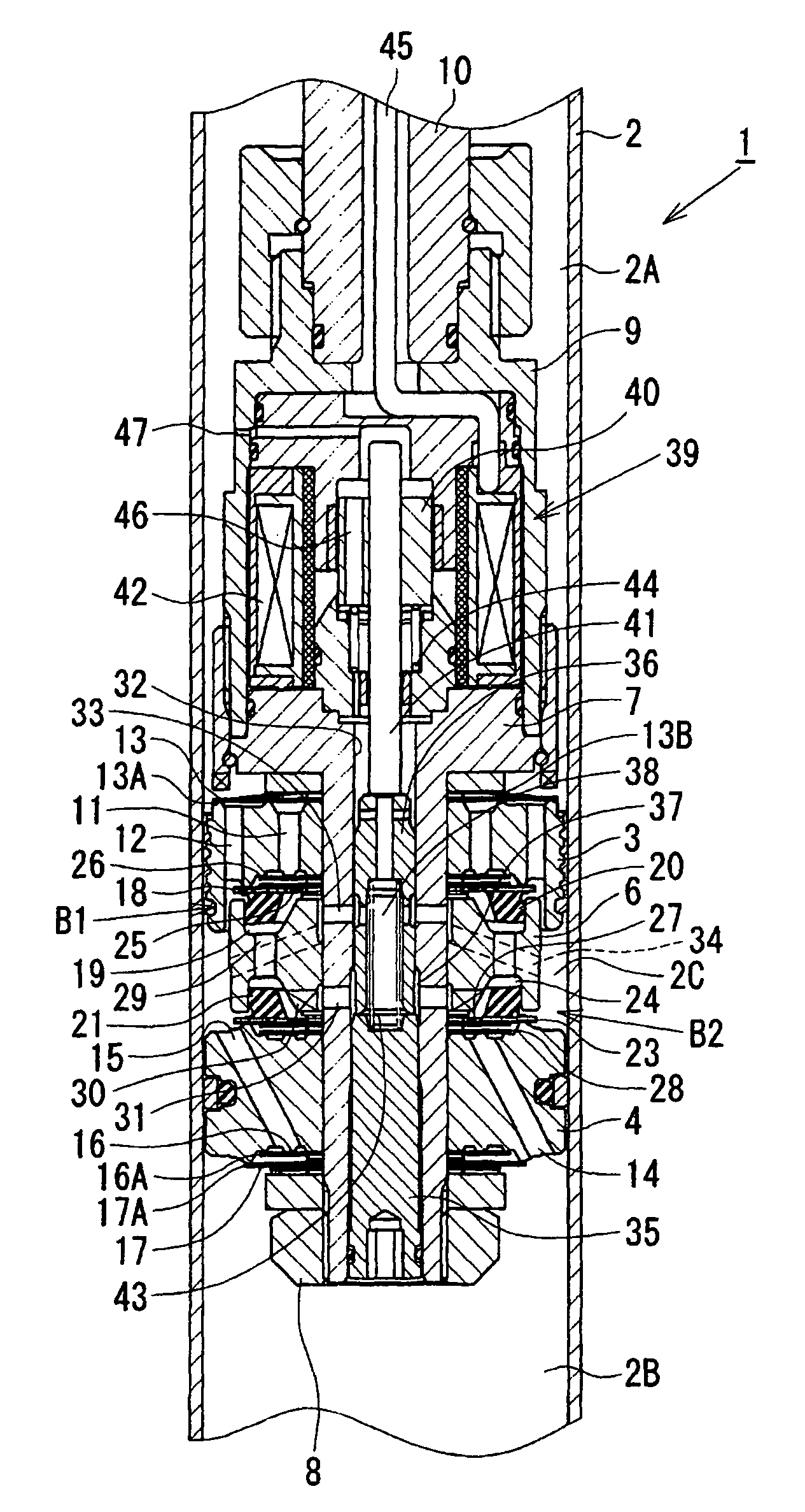
[0057]The first embodiment configured as described above works as follows. During an extension stroke of the piston rod 10, before the extension-side main valve 18 is opened, hydraulic fluid of the cylinder upper chamber 2A side flows through the orifice 13A of the compression-side check valve 13 and the compression-side passage 12 into the intermediate chamber 2C side. In addition, until the extension-side main valve 18 is opened, the hydraulic fluid of the cylinder upper chamber 2A side flows through the circular hole of the compression-side check valve 13, which is provided at a position facing the extension-side passage 11, the extension-side passage 11, the check valve 26, the orifice hydraulic fluid passage 25 provided at the extension-side main valve 18, the extension-side backpressure chamber 19, the communication passage 29, the compression-side backpressure chamber 24, the hydraulic fluid passage 30, and the port 31 into the valve chamber 37. The hydraulic fluid sent into ...

second embodiment

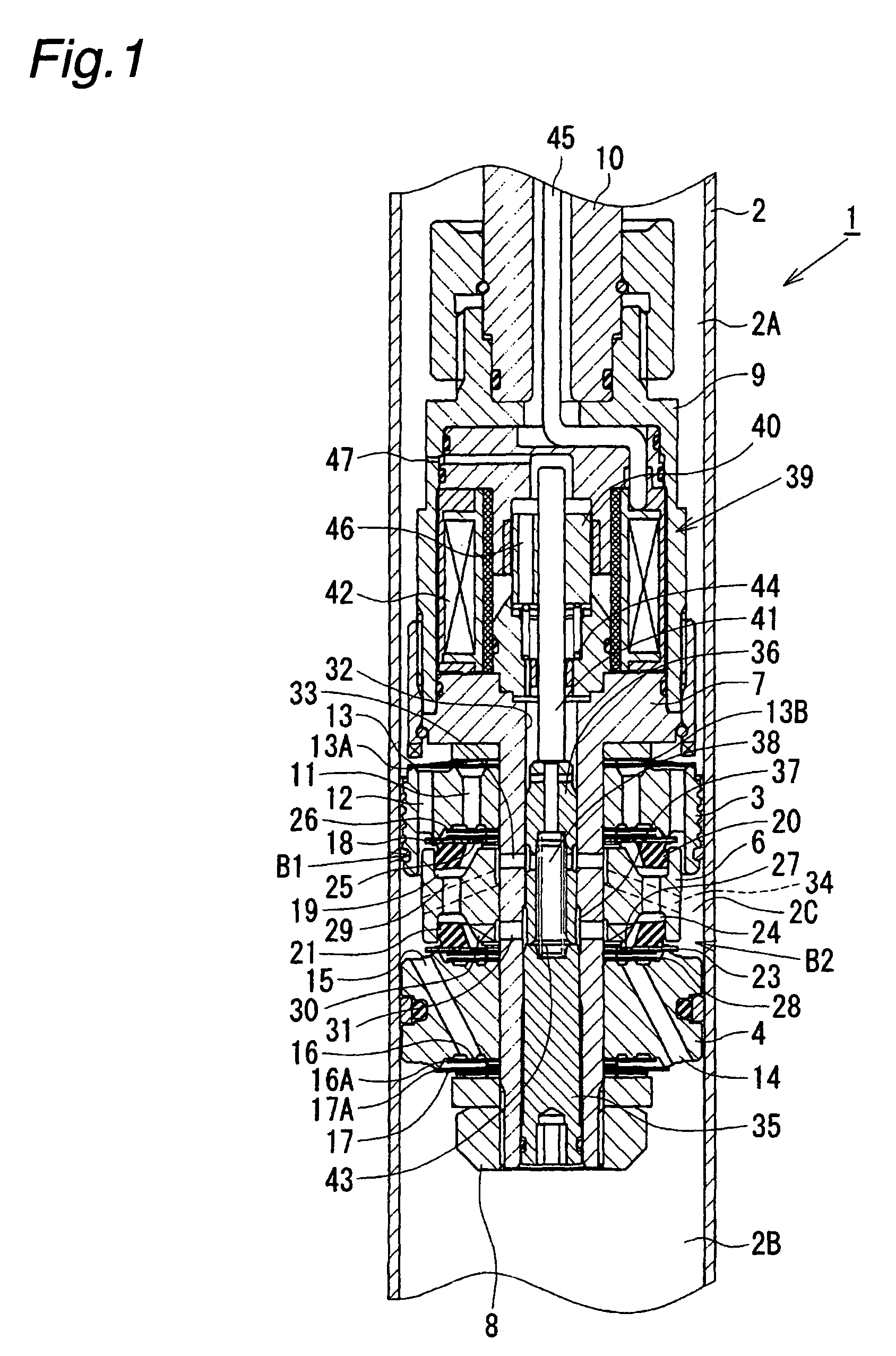
[0063]As shown in FIG. 2, in a hydraulic shock absorber 48 of the second embodiment, an extension-side backpressure chamber 19 is not in direct communication with a compression-side backpressure chamber 24, but is in communication with a guide bore 32 through an hydraulic fluid passage 49 of a valve member 6 and an extension-side port 50 provided through a side wall of a piston bolt 7. An extension-side damping force adjusting valve 51, in addition to a (compression-side) damping force adjusting valve 36, is slidably fitted in the guide bore 32. While the damping force adjusting valve 36 works to open and close the communication between a (compression-side) port 31 and a port 33, the damping force adjusting valve 51 works to open and close the communication between the extension-side port 50 and the port 33. The extension-side damping force adjusting valve 51 is interposed between the (compression-side) damping force adjusting valve 36 and an actuating rod 41. A distal end of the ex...

fourth embodiment

[0069]As shown in FIG. 4, in a hydraulic shock absorber 55 of the fourth embodiment, radially extending hydraulic fluid passages 34 are provided at an axial end of a first piston 3, instead of being provided at a valve member 6. Each radially outer end of the radially extending hydraulic fluid passages 34 is in communication with an intermediate chamber 2C through a compression-side passage 12. Each radially inner end of the radially extending hydraulic fluid passages 34 is in communication with a port 33 through a groove provided at an inner surface of the first piston 3. The radially extending hydraulic fluid passages 34 may be provided at an axial end of a second piston 4. In this case, the radially extending hydraulic fluid passages 34 may be provided such that a compression-side passage 15 and an internally provided hydraulic fluid passage 38 are in communication with each other through the passage 34.

[0070]The fourth embodiment configured as described above can bring about the...


PUM


Abstract

A first piston and a second piston coupled to a piston rod are fitted in a cylinder, and an intermediate chamber is formed between the first and second pistons. A compression-side check valve and an extension-side check valve are provided at the first piston and the second piston. An extension-side main valve and a compression-side main valve are disposed in the intermediate chamber. A downstream side of a damping force adjusting valve is connected to the intermediate chamber. Inner pressures of an extension-side backpressure chamber and a compression-side backpressure chamber are adjusted by the damping force adjusting valve, whereby valve opening of the extension-side and compression-side main valves is controlled. Hydraulic fluid of the downstream side of the damping force adjusting valve is first sent into the intermediate chamber, and then is sent to a cylinder upper chamber or a cylinder lower chamber. Due to this arrangement, it is possible to prevent a sudden drastic change in a hydraulic fluid pressure and thereby to generate a stable damping force.

Description

BACKGROUND OF THE INVENTION[0001]The present invention relates to a damping force adjustable fluid pressure shock absorber in which damping force characteristics can be appropriately adjusted.[0002]As a hydraulic shock absorber mounted on a suspension apparatus of a vehicle such as an automobile, there is known a damping force adjustable hydraulic shock absorber in which damping force characteristics can be appropriately adjusted in accordance with road surface conditions, vehicle running conditions, and the like, so as to improve ride comfort and steering stability.[0003]Generally, a damping force adjustable hydraulic shock absorber comprises a cylinder in which a hydraulic fluid is sealingly contained, a piston rod, and a piston coupled to the piston rod. The piston is slidably fitted in the cylinder so as to divide the inside of the cylinder into two chambers. The piston includes a primary hydraulic fluid passage and a bypass passage through which the two chambers in the cylinder...

Claims


Application Information

Patent Timeline
Patent Type & Authority Patents(United States)
IPC IPC(8): F16F9/34
CPCF16F9/465F16F9/3485F16F9/34F16F9/46
Inventor HAYAMA, HIROYUKIKATAYAMA, YOHEINEZU, TAKASHI
Owner HITACHI LTD
Why Eureka
Try Eureka