Eureka AIR delivers breakthrough ideas for toughest innovation challenges, trusted by R&D personnel around the world.
Shock absorber
Inactive Publication Date: 2014-07-03
YAMAHA MOTOR HYDRAULIC SYST
View PDF0 Cites 1 Cited by
Summary
Abstract
Description
Claims
Application Information
AI Technical Summary
This helps you quickly interpret patents by identifying the three key elements:
Problems solved by technology
Method used
Benefits of technology
The present invention provides a shock absorber that allows for easy disassembly and assembly of its components, and also ensures a high degree of coincidence between the axis lines of piston rods on either side of the piston. This results in a stable damping force.
Problems solved by technology
However, it is not easy that a pair of piston rods, which are separate members, are coupled to each other with their axis lines being coincident, as pointed out in Japanese Patent Application Laid-Open No. 2004-293720.
In the shock absorber disclosed in Japanese Patent Application Laid-Open No. 2004-293720, however, a structure to couple the piston rods is complicated, and there is a concern that the piston rod might not be maintained in such a manner that its radial movement is allowed if a load is applied to a region between the piston and the piston rod.
Additionally, there is a problem that it is difficult to obtain an advantageous effect of improved operability (smoothness of a load change in the course of displacement of the piston) when the pair of piston rods, which are not fixed to each other, are deviated from each other in the radial direction.
This inevitably makes it less easy to enhance the degree of coincidence between axis lines of the pair of piston rods.
That is, it has been conventionally difficult to achieve both facilitation of disassembling or assembling operations such as rearrangement of plate members and ensuring of the degree of coincidence between axis lines of piston rods.
Method used
Image
Click on the blue label to locate the original text in one second.
Reading with bidirectional positioning of images and text.
Examples
first preferred embodiment
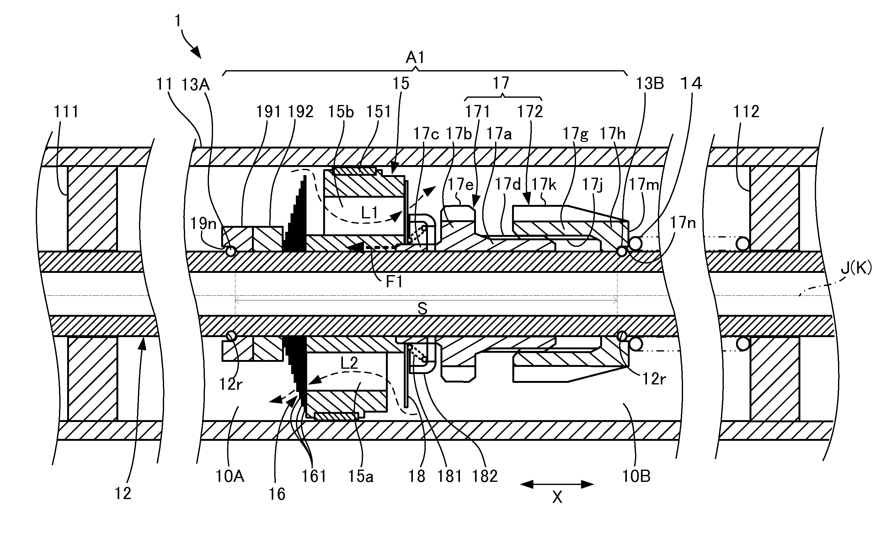
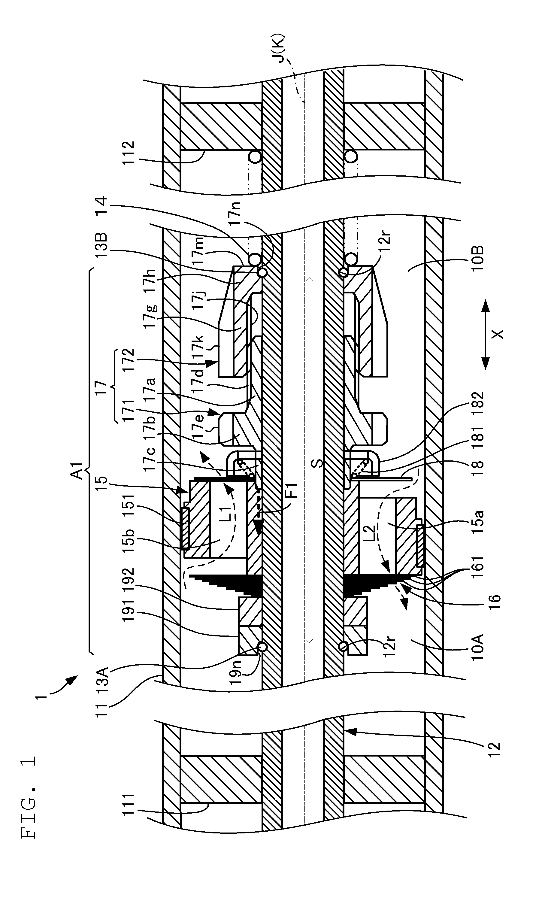
[0038]FIG. 1 is a cross-sectional view schematically showing a principal portion of a shock absorber according to a first preferred embodiment of the present invention. A shock absorber 1 shown in FIG. 1 is, for example, provided in a vehicle, and damps vibrations caused in the vehicle. The shock absorber 1 may be provided in a motorcycle, for example. The shock absorber of preferred embodiments of the present invention may be provided in an automobile or the like.
[0039]The shock absorber 1 includes a cylinder portion 11, a piston rod portion 12, a pair of fixing clips 13A, 13B, and a piston valve assembly A1. The pair of fixing clips 13A, 13B are shown as one example of a pair of protruding members according to a preferred embodiment of the present invention.
[0040]The cylinder portion 11 has a cylindrical shape. An axis line K of the cylinder portion 11 is shown in the center of FIG. 1. A pair of closures 111, 112 to close openings of the cylinder portion 11 are provided at both en...
second preferred embodiment
[0089]Next, a second preferred embodiment of the present invention will be described.
[0090]In the description of the second preferred embodiment given below, the same elements as those of the above-described preferred embodiment will be denoted by the same reference characters, or the reference characters will be omitted and differences from the above-described first preferred embodiment will be described.
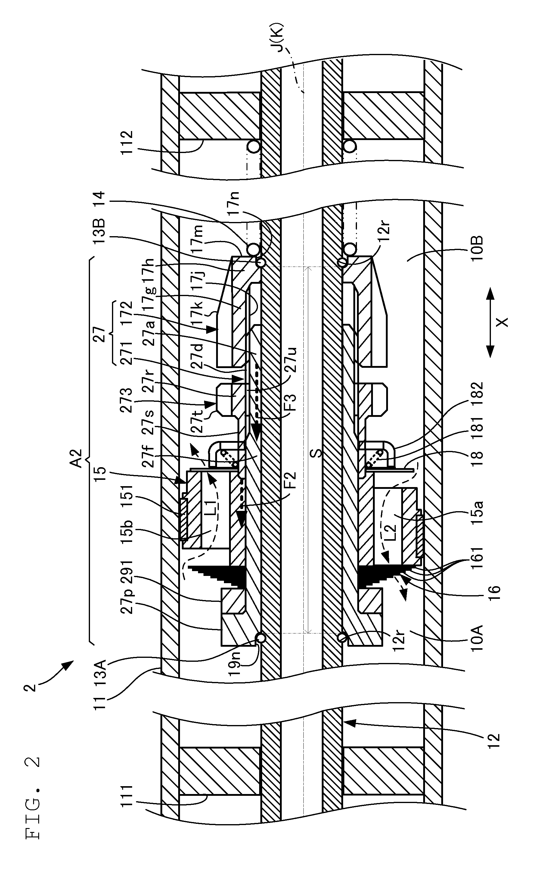
[0091]FIG. 2 is a cross-sectional view schematically showing a principal portion of a shock absorber according to the second preferred embodiment.
[0092]In a shock absorber 2 shown in FIG. 2, the piston portion 15, the damping valve element 16, and a threaded portion 27 are separate members. A piston valve assembly A2 includes a fastening thread member 273 in addition to the threaded portion 27. In the shock absorber 2, a male thread member 271 included in the threaded portion 27 has a length longer than the male thread member 171 of the first preferred embodiment shown in FIG. 1 wi...
PUM
Abstract
A shock absorber includes a cylinder portion, a piston rod portion arranged as a single member, a pair of protruding members protruding from an outer circumferential surface of the piston rod portion, and a piston valve assembly having the piston rod portion passing therethrough. The piston valve assembly includes a piston portion, a valve element, and a threaded portion arranged to extend or contract in an axial direction as a result of rotation of a female thread portion relative to a male thread portion. The piston valve assembly is arranged such that the piston portion and the valve element are retained to the piston rod portion so as not to move with respect to the axial direction of the piston rod portion by a stretching force generated between the pair of protruding members due to extension of the threaded portion.
Description
BACKGROUND OF THE INVENTION[0001]1. Field of the Invention[0002]The present invention relates to a shock absorber.[0003]2. Description of the Related Art[0004]Japanese Patent Application Laid-Open No. 2004-293720 discloses a shock absorber including a double rod cylinder. The shock absorber disclosed in the Japanese Patent Application Laid-Open No. 2004-293720 includes a cylinder, a piston, and a pair of piston rods. The piston, which is provided in the cylinder, partitions the interior of the cylinder into two oil chambers. A damping valve is provided in the piston. The damping valve allows communication between the two oil chambers. The piston rods are arranged on opposite surfaces of the piston. One piston rod extends from the piston in the axial direction of the cylinder, and protrudes out of the cylinder through an opening provided at one end of the cylinder. The other piston rod extends in the direction opposite to the direction of extension of the one piston rod. Similarly to...
Claims
Application Information
Patent Timeline
Application Date:The date an application was filed.
Publication Date:The date a patent or application was officially published.
First Publication Date:The earliest publication date of a patent with the same application number.
Issue Date:Publication date of the patent grant document.
PCT Entry Date:The Entry date of PCT National Phase.
Estimated Expiry Date:The statutory expiry date of a patent right according to the Patent Law, and it is the longest term of protection that the patent right can achieve without the termination of the patent right due to other reasons(Term extension factor has been taken into account ).
Invalid Date:Actual expiry date is based on effective date or publication date of legal transaction data of invalid patent.