Plasma generator, manufacturing method of rotating electrode for plasma generator, method for performing plasma treatment of substrate, and method for forming thin film having mixed structure by using plasma
- Summary
- Abstract
- Description
- Claims
- Application Information
AI Technical Summary
Benefits of technology
Problems solved by technology
Method used
Image
Examples
experimental example 1
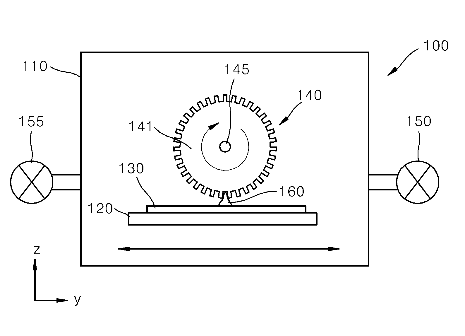
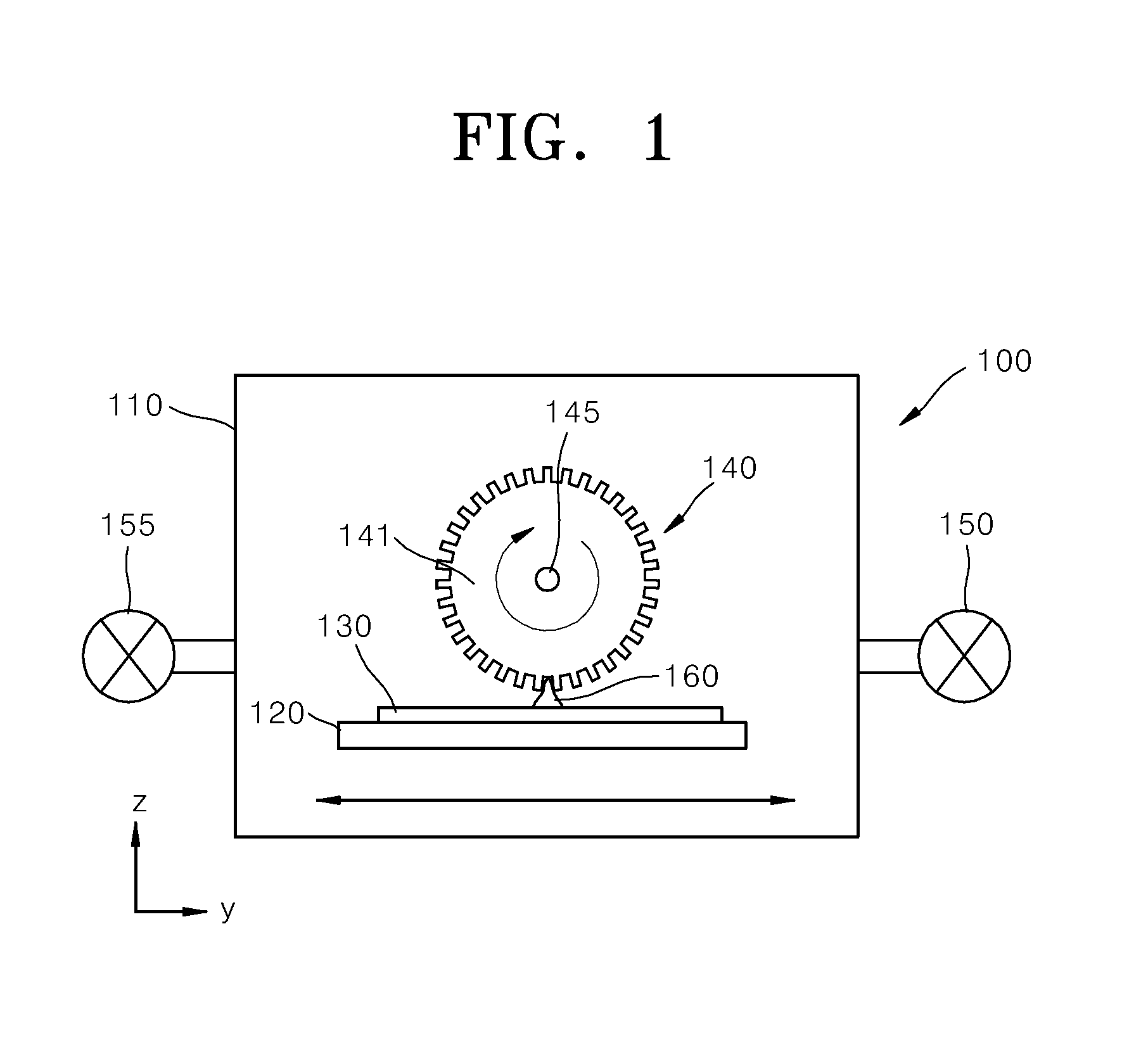
[0124]FIG. 8 shows the result of OES analysis of a plasma measured according to an experimental example of the present invention, wherein the shield layer 144 on the lower surface 143a of the capillary unit 143 to induce the effect of the present invention. The same plasma generator as that of FIG. 1 was used in this experimental example.
[0125]Referring to FIG. 8, various sub-peak wavelengths as well as the peak wavelength (706.5 nm) of helium were observed.
[0126]FIG. 9 shows plasma emission intensity of the peak wavelength of 706.5 nm of helium versus pressure for the comparative examples and experimental example.
[0127]Referring to FIG. 9, at a pressure of 300 Torr as above, a plasma intensity of approximately 9 times greater than that of plasma generated with a conventional rotating electrode on which no capillary units were formed was observed.
[0128]Meanwhile, FIG. 31 is a graph showing analysis of a degree of crystallinity of a silicon thin film formed by plasma generating from ...
PUM
| Property | Measurement | Unit |
|---|---|---|
| Width | aaaaa | aaaaa |
| Width | aaaaa | aaaaa |
| Dielectric polarization enthalpy | aaaaa | aaaaa |
Abstract
Description
Claims
Application Information
 - R&D
- Intellectual Property
- Life Sciences
- Materials
- Tech Scout
- Unparalleled Data Quality
- Higher Quality Content
- 60% Fewer Hallucinations
Browse by: Latest US Patents, China's latest patents, Technical Efficacy Thesaurus, Application Domain, Technology Topic, Popular Technical Reports.
© 2025 PatSnap. All rights reserved.Legal|Privacy policy|Modern Slavery Act Transparency Statement|Sitemap|About US| Contact US: help@patsnap.com


