Power beating device

a power beating and power technology, applied in the field of power beating devices, can solve the problems of unstable power, heavy power consumption, and unstable power, and achieve the effect of reducing weight and improving power efficiency

Active Publication Date: 2010-07-20
JELLEY TECH
View PDF23 Cites 9 Cited by
  • Summary
  • Abstract
  • Description
  • Claims
  • Application Information

AI Technical Summary

Benefits of technology

[0004]In the present invention, an inclined plane principle is used for improving power efficiency and reduce the weight is disclosed. A power beating device using an inclined plane comprises: a driving unit has a spring for storing and releasing energy so as to drive an impact unit; wherein the driving unit has at least one driving surface; an actuator serves to actuate the driving surface so that the impact unit is lifted with the driving unit, and the spring deform to store energy; when the impact unit is lifted to a predetermined height, it will rest and then the spring will release energy to drive the impact unit 40 to have the effect of beating. Thus the prior linear driving by using electromagnet or the rotation driving by using motor to convert into simple harmonic reciprocating motion are improved by the present invention so that it can resist against the energy storage unit instead of an operation by an inefficiency energy storage process.
[0005]Another object is to use a proper height h and an elastic coefficient k to control an output torque of a motor so that the output torque of the motor is retained with a constant value and meanwhile, the rotation speed, current, and output torque of a motor is controllable. Thus the rated power of the motor is reduced and thus the sizes of the motor and battery are also reduced. Further, the height h and the elastic coefficient k are designed to improve the efficiency of the motor and save power.
[0006]To achieve about object, the present invention provides a power beating device which is installed with a driving unit. The driving unit 2 is a round cylinder which is driven by an actuator 30. A driving surface 11 of the driving rotary cylinder 10 is an helical surface. The helical angle θ thereof is varied with a height h. The height is increased in the rotation direction. When the height achieves to a maximum displacement of a spring, then the height is reset. When the driving unit 2 moves, an impact unit 40 is lifted with the driving surface 11 of the driving unit 2. The spring 20 also stores energy. The increment of the driving surface 11 of the driving unit 2 is designed to make the driving resisting force in the energy storage process is wholly controlled manually. That is to say, the user can control the power supply curve of a motor. For example, the height of the driving surface 11 of the driving unit 2 is designed properly so that the time variation of the increment of the height (Δh / Δt) is increased with the resistance force (f) of the displacement (Δs) of the spring 20, and then the output torque of the motor is retained to a constant value. Furthermore, the rotation speed, current, output torque, and efficient of the motor is controllable. Thus the rated power of the motor is reduced and thus the sizes of the motor and battery are also reduced. Further, the height h and the elastic coefficient k are designed to improve the efficiency of the motor and save power.

Problems solved by technology

However the defects of the electromagnetic driving are heavy and power consumed, while the simple harmonic motion from the rotation movement of a motor is that the power is unstable, especially when the impact unit moves to an impact position driving the nail, the spring needs a great driving force, but at this moment, the simple harmonic motion from the rotation movement of a motor is at a maximum value in the sinusoidal moving curve.
However the flywheel consumes more power and is uneconomic.
However all these devices will make the device complicated and can not improve the prior art defect effective.

Method used


Image

  • Power beating device
  • Power beating device
  • Power beating device

Examples


Embodiment Construction

[0018]In order that those skilled in the art can further understand the present invention, a description will be provided in the following in details. However, these descriptions and the appended drawings are only used to cause those skilled in the art to understand the objects, features, and characteristics of the present invention, but not to be used to confine the scope and spirit of the present invention defined in the appended claims.

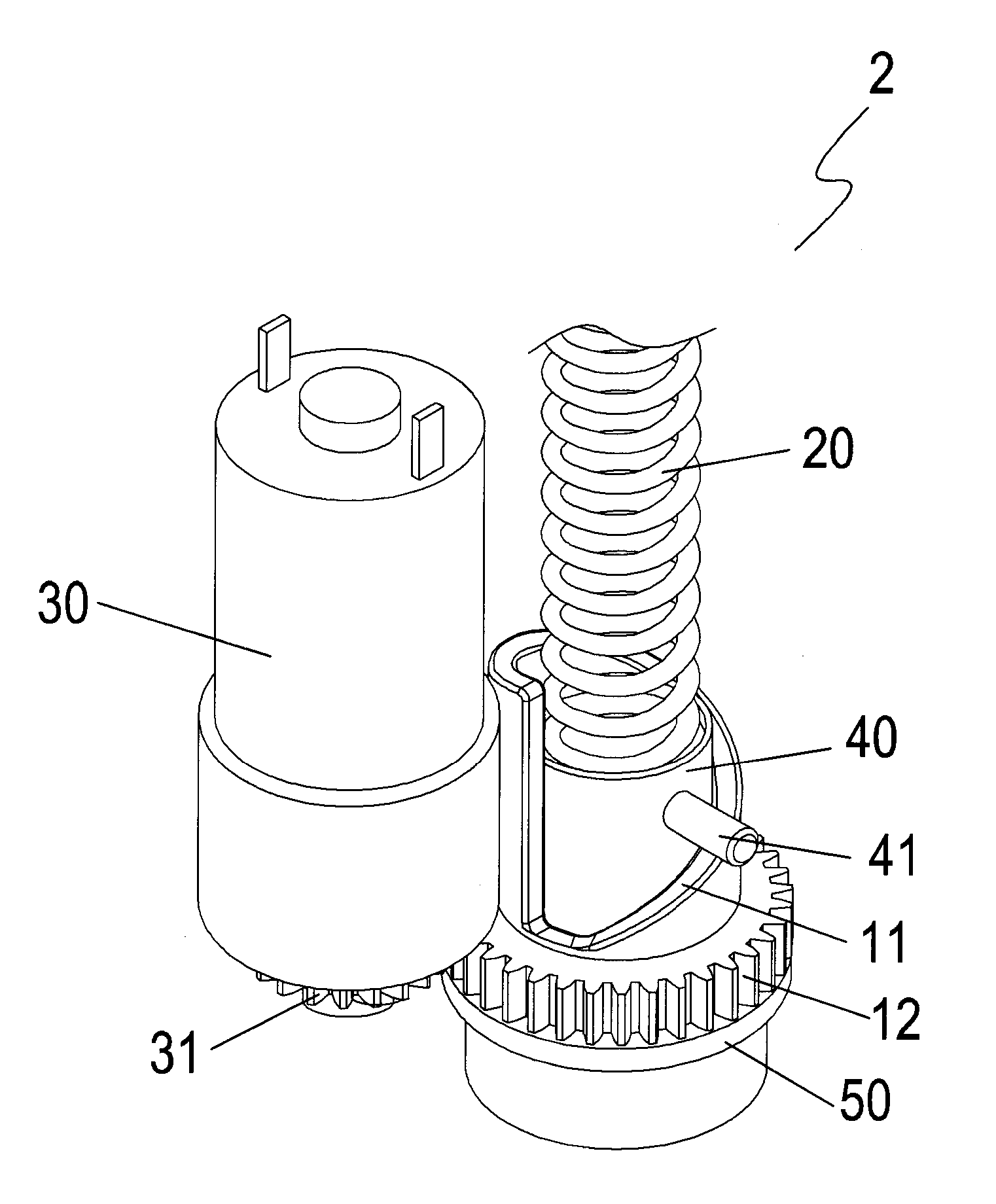
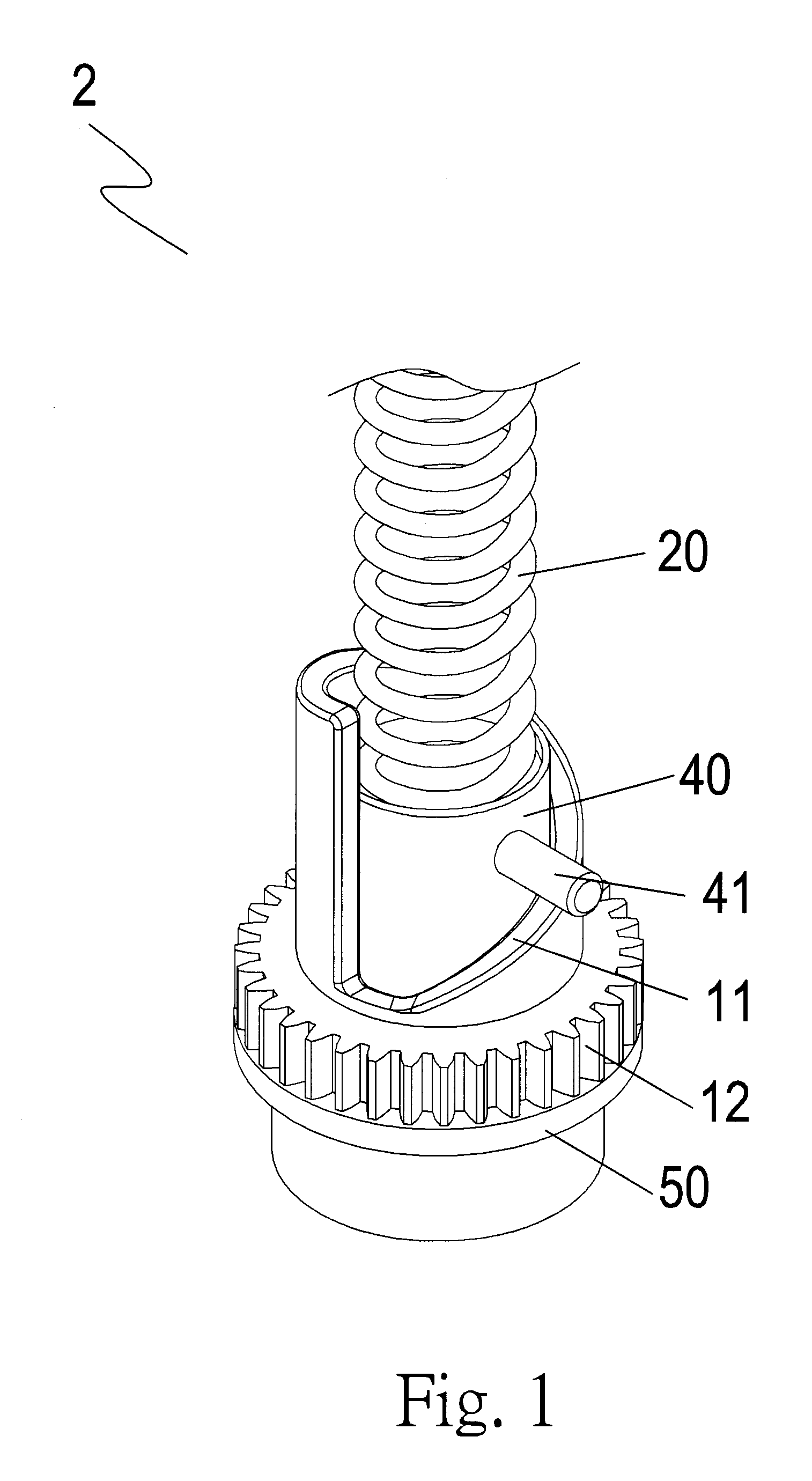
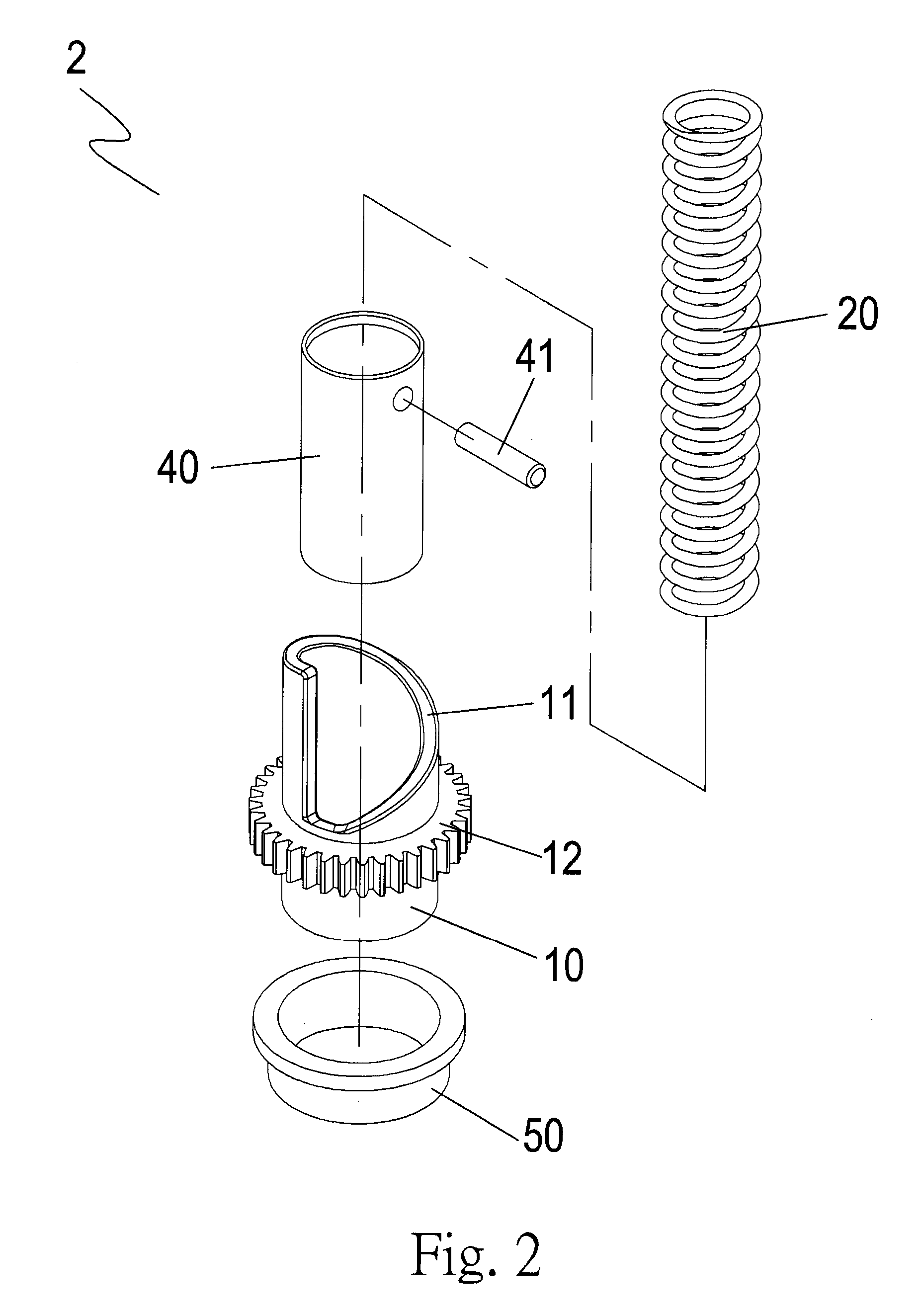
[0019]With referring to FIGS. 1 and 2, the power beating device of the present invention includes the following elements.

[0020]A set of driving unit 2 has a spring 20 for storing and releasing energy, an impact unit 40, a driving rotary cylinder 10 and a driving bush 50. The spring 20 drives an impact unit 40. The driving pin 41 inserts into the impact unit 40. The driving rotary cylinder 10 has a driven gear 12 at an outer periphery thereof and a wedge helical driving surface 11 above the driven gear 12. The driving bush 50 is installed at a lower...


PUM


Abstract

A power beating device using includes a driving unit and an actuator. The driving unit has a spring for storing and releasing energy so as to drive an impact unit. The driving unit has at least one driving surface. The actuator serves for actuating the driving surface so that the impact unit is lifted with the driving unit. Deformation of the spring will store energy. When the impact unit is lifted to a predetermined height, it will rest and then the spring will release energy to drive the impact unit to have the effect of beating.

Description

FIELD OF THE INVENTION[0001]The present invention relates to a power beating device, and particularly to a power beating device used in a nail or staple driver, which has a set of driving unit containing a spring as an energy storage and releasing devices for driving an impact unit.BACKGROUND OF THE INVENTION[0002]Generally, a power beating device uses a driving unit, such as a liner movement of an electromagnet or a simple harmonic motion from the rotation movement of a motor, to resist against an energy storage unit, for example to use a spring to cause an impact unit to move from a first position to a second position so as to store the potential energy from electric energy. When the spring moves to a second position, the storage energy is converted into the dynamic energy of the impact unit so as to drive a nail into a work piece. The requirement of this kind of power beating device is that it must be light and power saved. However the defects of the electromagnetic driving are h...

Claims


Application Information

Patent Timeline
Patent Type & Authority Patents(United States)
IPC IPC(8): B25C1/00
CPCB25C1/06B25C5/10
Inventor WANG, FENG-HO
Owner JELLEY TECH
Why Eureka
Try Eureka