Discharge tube and lamp with cooling chambers and improved luminance

a discharge tube and cooling chamber technology, applied in the direction of discharge tube main electrodes, discharge tube luminescnet screens, incadescent cooling arrangements, etc., can solve the problems of insufficient cooling chamber configuration, inability to provide the same effect, distribution of lamps, etc., to improve luminous output, improve wattage, and facilitate formation

Inactive Publication Date: 2010-07-20
GENERAL ELECTRIC CO
View PDF14 Cites 0 Cited by
  • Summary
  • Abstract
  • Description
  • Claims
  • Application Information

AI Technical Summary

Benefits of technology

[0009]The discharge tube and lamp with the second cold chamber portion has an improved luminous output in a base-down or horizontal position of the lamp. The light output of a compact fluorescent lamp of a relatively higher wattage can be increased by more than 10% using the second cold chamber. The second or further cold chambers on tube portions of the discharge tube may be easily formed with known manufacturing steps.

Problems solved by technology

Such a cold chamber configuration will not provide the same effect when using the lamp in the upright or downward position.
However, the light distribution of the lamp in the region of the cold chamber still needs improvement, because a relative large portion of the enveloping surface is not utilized as lighting surface, particularly in the direction along the axis of the lamp, towards the end which is further away from the lamp housing.
Again, the lamp does not provide the same luminous output if it operates in a base-down position.

Method used


Image

  • Discharge tube and lamp with cooling chambers and improved luminance
  • Discharge tube and lamp with cooling chambers and improved luminance
  • Discharge tube and lamp with cooling chambers and improved luminance

Examples


first embodiment

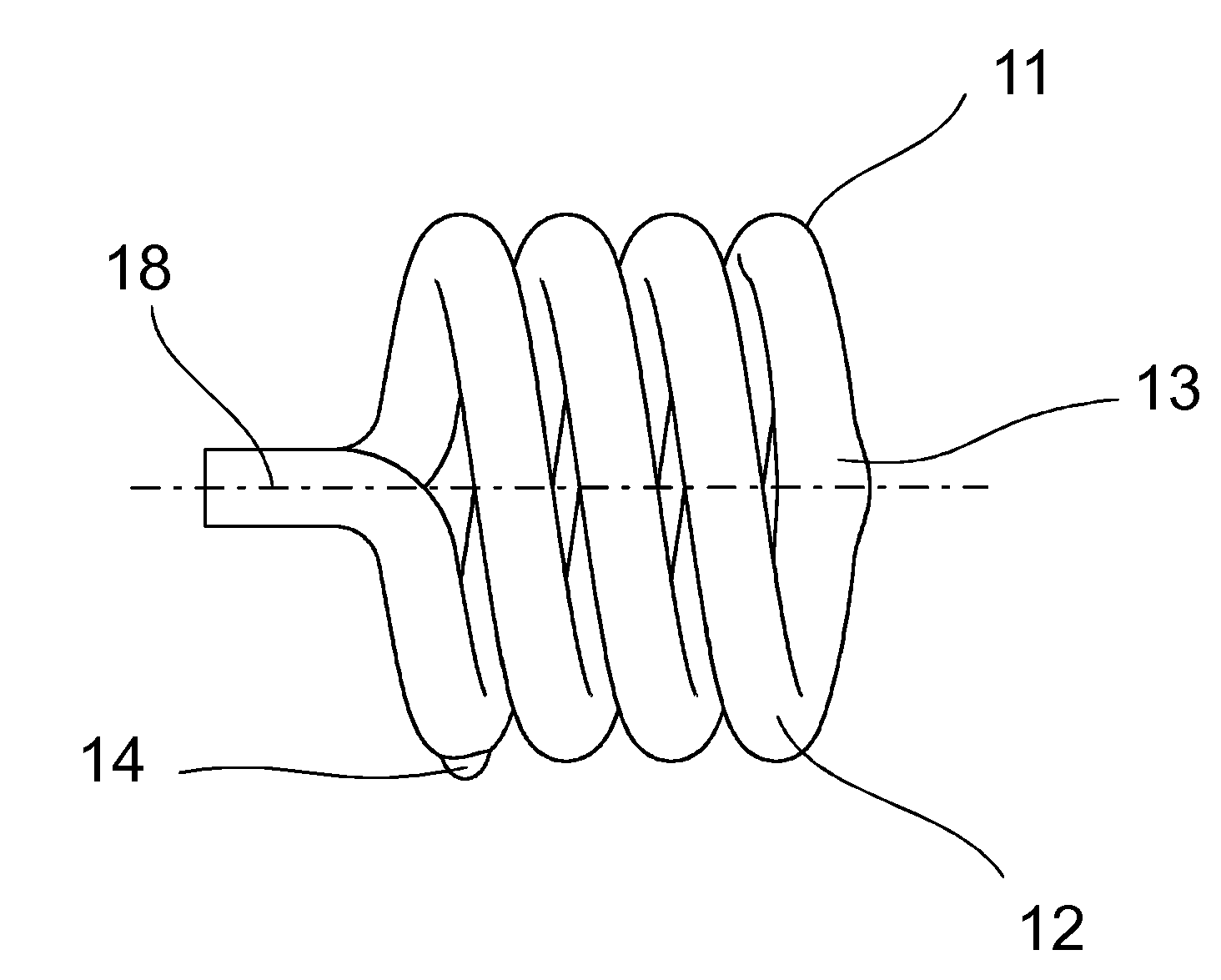
[0025]In the invention, as shown in FIGS. 4 to 7, the discharge tube arrangement 10 has a helical form comprising a single tube with substantially straight end sections 15, 16 and an intermediate portion comprising two helical tube members 11, 12 between the end sections. The end sections 15, 16 are at one end of the tube arrangement and in proximity to each other and the intermediate portion has a coiled configuration wound about the central axis 18 of the discharge tube arrangement 10. In the shown embodiment, the individual coil members of the helical tube have substantially the same diametrical dimension. The tube has a substantially circular cross section with a substantially constant cross sectional dimension. The end sections 15, 16 of the tube are closed by a gas tight sealing and comprise an electrode assembly in order to produce a discharge arc within the tube. The tube is filled with a discharge gas such as for example argon for maintaining the discharge. Mercury is added...

second embodiment

[0037]In a second embodiment, as illustrated in FIGS. 8 to 11, the discharge tube arrangement 30 is comprised of straight tube members 31, 32 with a longitudinal axis substantially parallel to the central axis 38 of the fluorescent lamp and the neighboring tube members being connected to each other in series to form a continuous arc path. The tube members 31, 32 have a substantially circular cross section with a substantially constant cross sectional dimension. The end sections of the tube are closed by a gas tight sealing and comprise an electrode assembly in order to produce a discharge arc within the tube. The tube is tilled with a discharge gas for maintaining the discharge. Mercury is added to the discharge gas in order to generate UV radiation when a discharge is present within the tube. The inside wall of the discharge tube is covered with a luminescent layer, typically a blend of different phosphor components that converts UV radiation into visible light. The first cold camb...


PUM


Abstract

A discharge tube arrangement for a compact fluorescent lamp is provided. The tube forms a continuous arc path and has electrodes disposed at each end of the arc path. The discharge tube arrangement comprises a first cold chamber in order to control and maintain a required mercury vapor pressure. The first cold chamber is located in a longitudinal end portion of the tube arrangement. The discharge tube arrangement is further provided with at least one second cold chamber, which is positioned between the longitudinal end portions of the discharge tube arrangement. The at least one second cold chamber is positioned on the wall of the tube, and has a cold chamber wall protruding substantially away from the central axis of the discharge tube arrangement. The discharge tube arrangement may have a coiled configuration with helical tube portions or a multifinger configuration with straight tube members.

Description

FIELD OF THE INVENTION[0001]This invention relates to a low-pressure discharge lamp with improved luminance. The discharge lamp comprises a discharge tube enclosing a discharge volume. The discharge tube has sealed ends and is provided with means for generating and sustaining a discharge within the discharge volume. The lamp is further provided with a cold chamber portion in order to control and maintain a partial mercury pressure.BACKGROUND OF THE INVENTION[0002]Low-pressure discharge lamps are well known in the art. These lamps contain small doses of mercury, which radiates in the short range UV spectrum under the influence of a discharge arc. In order to achieve maximum luminous output or luminance, it is required that the mercury vapor is adjusted and stabilized at a well-defined partial pressure. This is possible by forming a so-called cold chamber on the discharge tube, and by selecting the appropriate temperature in the cold chamber, which is the coldest point of the gas disc...

Claims


Application Information

Patent Timeline
Patent Type & Authority Patents(United States)
IPC IPC(8): H01J1/02H01J7/24
CPCH01J61/28H01J61/327Y02B20/19Y02B20/00
Inventor CSERTEG, ERZSEBETTALOSI, KAROLYSITI, ARNILIU, ZHIFUSCHMIDT, GABORORBAN, JANOSSESZTAK, TIMEA
Owner GENERAL ELECTRIC CO
Why Eureka
Try Eureka