Methods and systems for message transfer part (MTP) load sharing using MTP load sharing groups

a message transfer and load sharing technology, applied in the field of methods and systems for load sharing signaling messages, can solve the problems of limited load sharing messages between these nodes, the inability to send route-on-pc-ssn load sharing messages, and the significant disadvantage of terminating network operators

Active Publication Date: 2010-07-20
TEKELEC GLOBAL INC
View PDF55 Cites 5 Cited by
  • Summary
  • Abstract
  • Description
  • Claims
  • Application Information

AI Technical Summary

Benefits of technology

[0007]The subject matter described herein includes methods and systems for load sharing signaling message traffic among signaling nodes in an MTP load sharing group. According to one method, a signaling message that is marked route-on-PC-SSN is received, and an MTP load sharing group is identified for the signaling message. The signaling message may then be load shared among destination nodes in the MTP load sharing group. Load sharing the signaling message among nodes in the MTP load sharing group may include replacing the destination point code in a message with an alternate destination point code. The ability to identify MTP load sharing groups for messages marked route-on-PC-SSN and replace destination point codes allows load sharing to be performed at the MTP level without requiring global title translation to be implemented.

Problems solved by technology

One problem associated with the above-described load sharing techniques is illustrated in FIG. 1.
The inability to load share messages sent route-on-PC-SSN can be a significant disadvantage for terminating network operators because the ability of these operators to deploy identically provisioned nodes and load share messages between these nodes is limited.

Method used


Image

  • Methods and systems for message transfer part (MTP) load sharing using MTP load sharing groups
  • Methods and systems for message transfer part (MTP) load sharing using MTP load sharing groups
  • Methods and systems for message transfer part (MTP) load sharing using MTP load sharing groups

Examples


embodiment 1

MTP Load Sharing Among Nodes in MTP Load Sharing Groups

[0019]In a first embodiment, message transfer part (MTP) load sharing is facilitated between a designated group of point code addresses. With this embodiment, a network operator may configure a group of point codes to be considered an MTP load sharing group, (MLG). The group members may be assigned relative weights, which may determine their hierarchical status within the group.

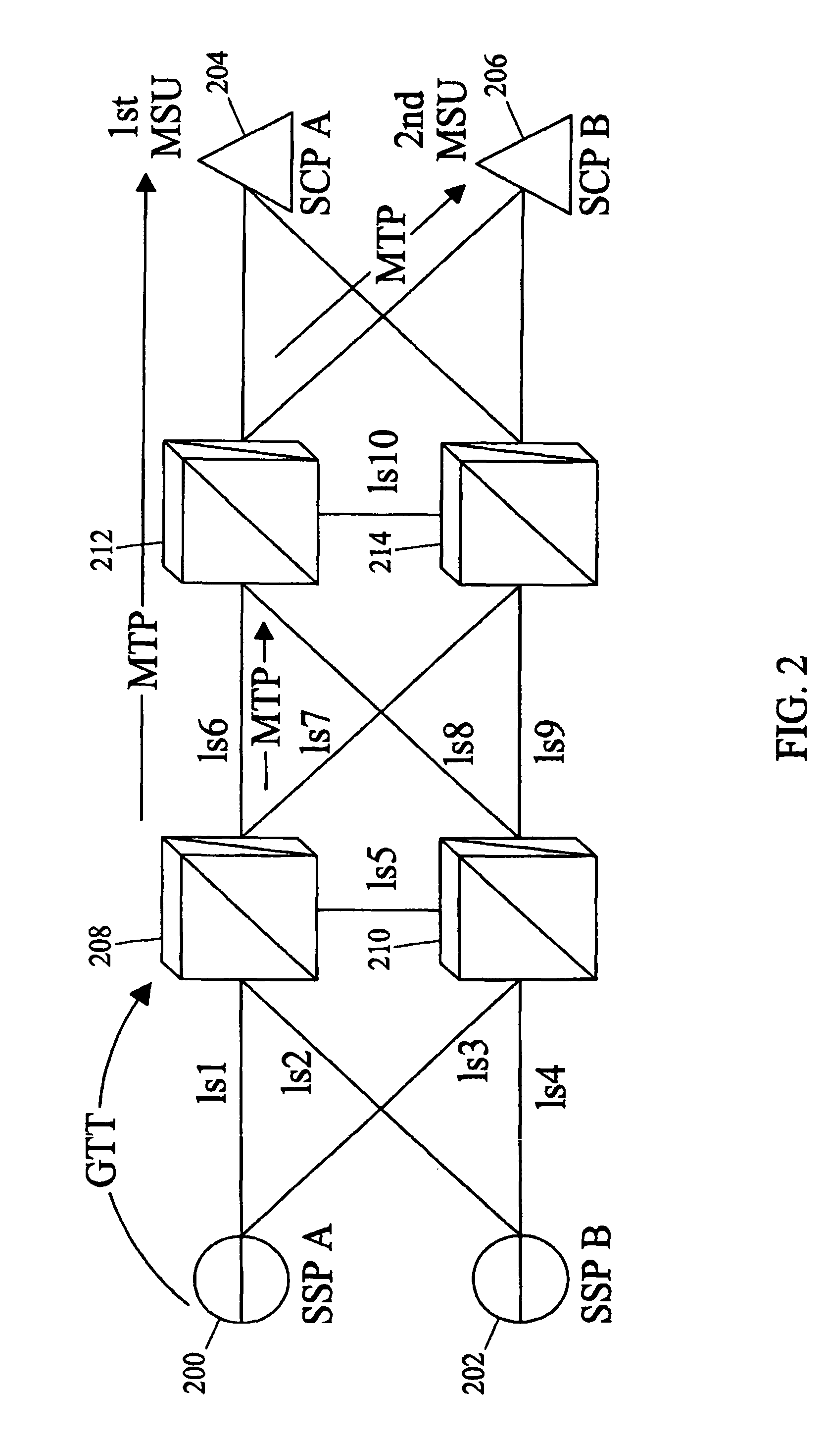
[0020]FIG. 2 is a network diagram illustrating load sharing among MTP load sharing groups according to an embodiment of the subject matter described herein. Referring to FIG. 2, SSPs 200 and 202 send messages to SCPs 204 and 206. The messages are initially sent route-on-global-title to either STP 208 or STP 210. STP 208 or STP 210 performs global title translation on the messages and changes the routing indicator in the messages to indicate that the messages are route-on-PC-SSN. STPs 212 and 214 receive messages destined to the point code of one of SCPs 2...


PUM


Abstract

Methods and systems for load sharing signaling messages at the MTP level are disclosed. When a signaling message is received, it is determined whether the signaling message includes a routing indication indicating route-on-point-code-subsystem-number. If the routing indicator indicates route-on-point-code-subsystem-number, it is determined whether the signaling message belongs to an MTP level 3 load sharing group. If the signaling message belongs to an MTP level 3 load sharing group, the signaling message may be routed to any of the point codes in the MTP level 3 load sharing group. Routing the signaling message to a point code in the MTP level 3 load sharing group may include replacing the destination point code in the signaling message with the destination point code of the node to which the signaling message is to be routed. Once the point code has been replaced, the signaling message is routed to the destination associated with the point code.

Description

RELATED APPLICATIONS[0001]This application claims the benefit of U.S. Provisional Patent Application Ser. No. 60 / 523,817, filed Nov. 20, 2003, the disclosure of which is incorporated herein by reference in its entirety.TECHNICAL FIELD[0002]The subject matter described herein relates to methods and systems for load sharing signaling messages. More particularly, the subject matter described herein relates to methods and systems for MTP load sharing signaling messages among point codes in MTP load sharing groups.BACKGROUND ART[0003]In order to route signaling system 7 (SS7) messages, network elements within an SS7 network must be configured with a routable network identity or address (e.g., a point code address) and routing or path information associated with other network elements witnin the network. One aspect of message routing in an SS7 network that is of particular interest with respect to the subject matter described herein involves the load sharing of signaling messages among mu...

Claims


Application Information

Patent Timeline
Patent Type & Authority Patents(United States)
IPC IPC(8): H04L12/66H04J3/12H04M7/06G06FH04L12/26H04Q3/00
CPCH04Q3/0025
Inventor DELANEY, ROBERT J.EICHLER, TODD
Owner TEKELEC GLOBAL INC
Why Eureka
Try Eureka