
Ultra-compact, high performance aerovortical rocket thruster

a rocket thruster, ultra-compact technology, applied in the field of low-thrust rocket propulsion thrusters, can solve the problems of inability to miniaturize the thruster system of small spacecraft, the rocket engine type is much too complicated, and the toxicity of hydrozine or mmh vapor, so as to broaden the scope of potential rocket engine thruster applications, improve the mixing and combustion process, and improve the propulsion performance

Inactive Publication Date: 2010-07-27
AEROJET ROCKETDYNE OF DE
View PDF58 Cites 7 Cited by
  • Summary
  • Abstract
  • Description
  • Claims
  • Application Information

AI Technical Summary

Benefits of technology

This design reduces the size and weight of the thruster while maintaining high propulsion performance, achieving thrust levels from 5 lbf to 250 lbf and improving specific impulse by reducing combustor length and weight, thus overcoming the limitations of traditional swirl vane designs.

Problems solved by technology

Because this is more difficult for larger spacecraft, propulsion thruster designs normally work with momentum (mv).
Again, hydrazine or MMH vapors are extremely toxic, requiring special handling and the use of two propellants somewhat complicates the propellant management for on-board spacecraft.
This type of rocket engine is much too complicated and cannot be miniaturized for implementing into small spacecraft thruster systems.
Furthermore, the swirl generator has no moving parts so the complexity of the engine and production cost is kept low.
However, current swirl vane designs are limited in their applicability to ultra-compact rocket engine designs due to their low-end size limitation.
For ultra-compact rocket engine designs that are, for example, less than about two inches in diameter, it is very difficult to fabricate, integrate and assemble individual swirl vanes into the vane pack.
This hampers practical application of swirl combustion technology into the ultra-compact rocket engine designs.

Method used


Image

  • Ultra-compact, high performance aerovortical rocket thruster
  • Ultra-compact, high performance aerovortical rocket thruster
  • Ultra-compact, high performance aerovortical rocket thruster

Examples


Embodiment Construction

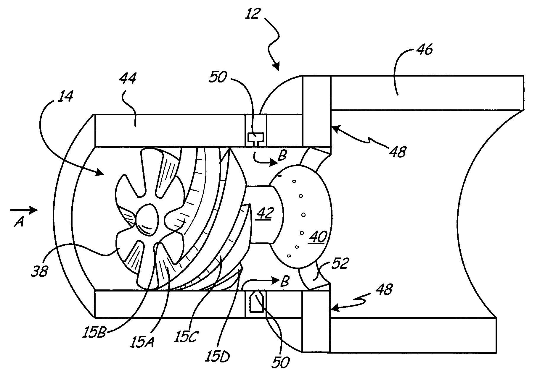
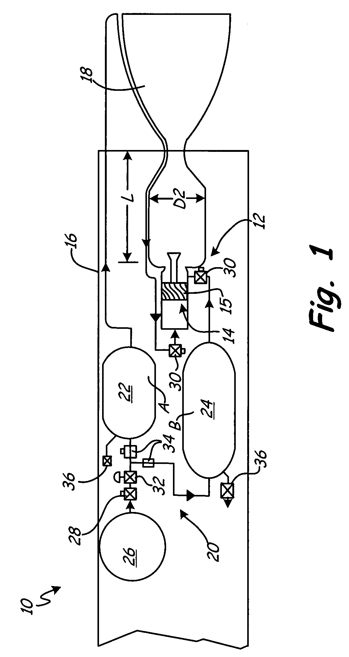
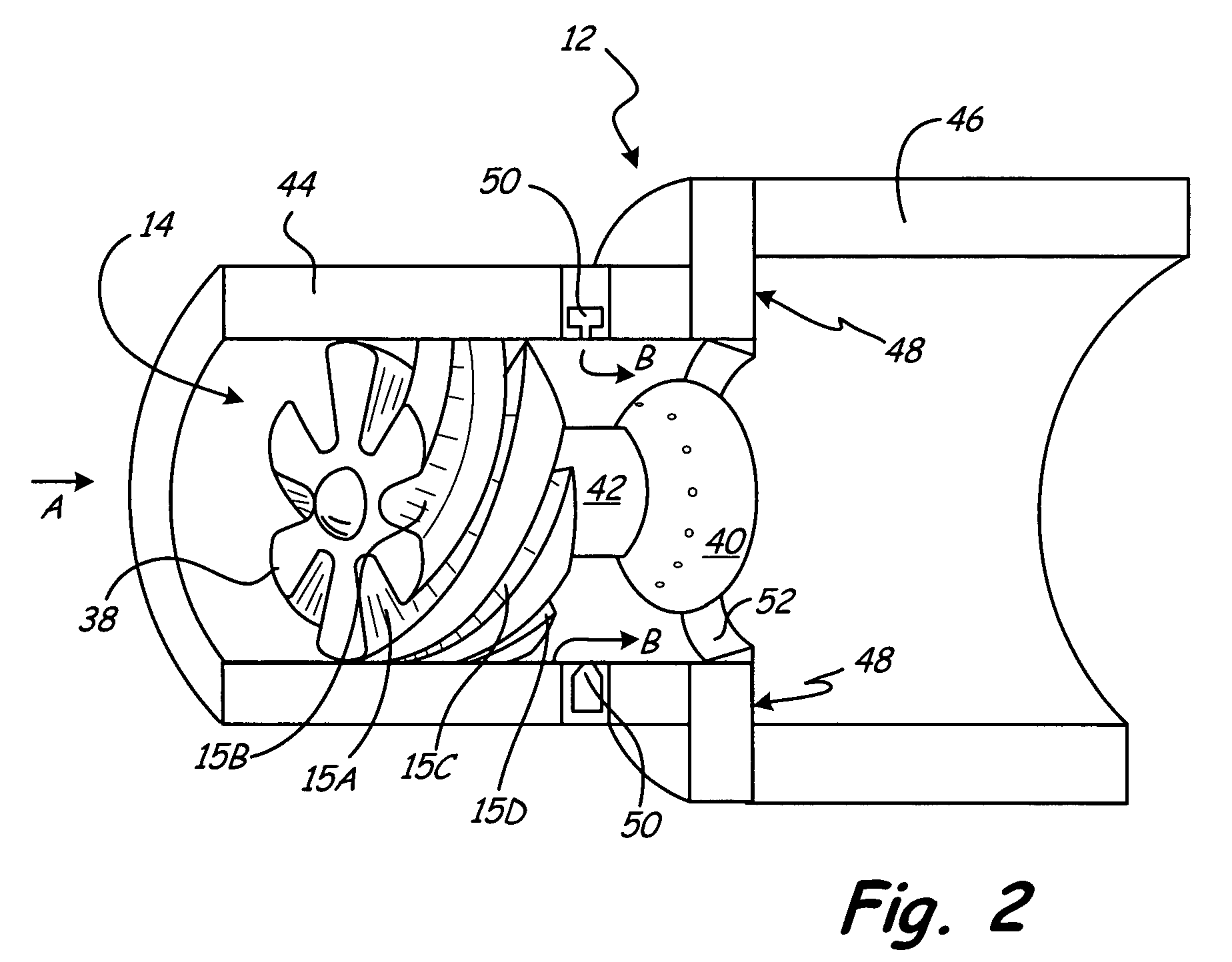
[0021]FIG. 1 shows a schematic of liquid bipropellant thruster 10 having aerovortical swirl-dump combustor 12 with ultra-compact, aerovortical swirl generator 14 having helicoid flow channels 15. Thruster 10 also includes thruster body 16, thrust nozzle 18 and gas pressure feed system 20, which can be configured for a variety of ultra-compact rocket engine applications; such as in-space satellite attitude and orbit control, in-space vehicle propulsion, or propulsion of some similar spacecraft. Thruster body 16 provides a housing for propellant constituent storage tanks 22 and 24, high pressure supply tank 26, high pressure gas valve (remote control) 28, propellant valves (remote control) 30, pressure regulator 32, check valves 34, and storage tank vent valves 36.

[0022]Rocket thruster 10 must carry an adequate supply of combustion constituents, typically an oxidizer and a fuel, for use in the combustion process necessary to generate thrust for propelling the spacecraft. Liquid fuel p...


PUM


Abstract

An ultra-compact aerovortical swirl-enhanced combustion (ASC) system features an aerovortical swirl generator for use in rocket thrusters utilizing hypergolic or non-hypergolic propellants. The ACS thruster can be sized for diameters ranging from about 0.5 to about 2.0 inches, and producing thrust levels of approximately 5 lbf to about 250 lbf. A plurality of helicoid flow channels in the swirl generator introduces swirl into a flow stream of a first propellant within ultra-compact sized rocket thrusters. The ASC system also includes injectors for introducing a second liquid propellant into the swirling flowfield to promote rapid and efficient atomization, mixing and vigorous combustion, which, results in major improvements in combustion and propulsion performance over current rocket thrusters, but in much shorter combustor systems. Hence, the ultra-compact ASC system is a substantial improvement in small bipropellant chemical propulsion thrusters, which can be utilized in-space satellite, spacecraft maneuvering and attitude / orbit control.

Description

BACKGROUND OF THE INVENTION[0001]This invention relates generally to low thrust rocket propulsion thrusters and more particularly to bipropellant chemical thrusters for in-space satellite attitude and orbit control and in-space vehicle propulsion.[0002]In-space propulsion thrusters are used to maneuver spacecraft (e.g. a satellite or space vehicle) after a launch vehicle has delivered it to the upper atmosphere. In general, the primary objective of a space propulsion thruster is to place the spacecraft into its intended orbit or maintain the spacecraft's proper position while in orbit. Specifically, onboard thrusters are used for orbit transfer; attitude pointing and control so that a spacecraft is correctly pointing towards the Earth, Sun or an astronomical object of interest; orbit altitude control; and station keeping. Thrust attitude control allows spacecraft to control the angular position while in orbit, which may be required for various sensors, transponders or other spacecra...

Claims


Application Information

Patent Timeline
Patent Type & Authority Patents(United States)
IPC IPC(8): F02K9/00
CPCF02K9/50F02K9/52F02K9/62F05D2250/25
Inventor PEDERSON, ROBERT J.SCHMOTOLOCHA, STEPHEN N.
Owner AEROJET ROCKETDYNE OF DE
Learn More