MEMS printhead based compressed fluid printing system

a fluid printing and printhead technology, applied in printing and other directions, can solve the problems of reducing the reliability of the printhead, limiting the viscosity range of the ink used in the printer, and disadvantaged conventional ink jet printers, so as to achieve low cost mass production and ensure operation.

Inactive Publication Date: 2010-07-27
EASTMAN KODAK CO
View PDF18 Cites 14 Cited by
  • Summary
  • Abstract
  • Description
  • Claims
  • Application Information

AI Technical Summary

Benefits of technology

[0019]An advantage of the present invention is that CMOS / VLSI materials and processes can be used to make micro-machined manifolds for printing with compressed fluids. This enables low-cost mass production of micro-machined manifolds. Another advantage is the simple sealing methods like clamped gaskets can be used to provide leak-proof connection between the micro-machined manifold and the high-pressure source. Another advantage of the present invention is that marking material and effluent gases that escape during printing can be collected to provide a safer operation. A further advantage is that a wide variety of materials including those using conventional solvents as co-solvents can be directly printed with the apparatus disclosed in this invention.
is that CMOS / VLSI materials and processes can be used to make micro-machined manifolds for printing with compressed fluids. This enables low-cost mass production of micro-machined manifolds. Another advantage is the simple sealing methods like clamped gaskets can be used to provide leak-proof connection between the micro-machined manifold and the high-pressure source. Another advantage of the present invention is that marking material and effluent gases that escape during printing can be collected to provide a safer operation. A further advantage is that a wide variety of materials including those using conventional solvents as co-solvents can be directly printed with the apparatus disclosed in this invention.

Problems solved by technology

Conventional ink jet printers are disadvantaged in several ways.
While the frequency of actuation reduces printhead reliability, it also limits the viscosity range of the ink used in these printers.
The increased liquid content results in slower ink dry times after the ink has been deposited on the receiver, and this decreases overall productivity.
Additionally, increased solvent content can also cause an increase in ink bleeding during drying which reduces image sharpness, negatively affecting image resolution and other image quality metrics.
For receivers such as plain paper, excessive liquid can also lead to local mechanical buckling of the receiver.
Conventional ink jet printers are also disadvantaged in that the discharge devices of the printheads can become partially blocked and / or completely blocked with ink.
In order to reduce this problem, solvents, such as glycol, glycerol, etc., are added to the ink formulation, which can adversely affect image quality.
This increases the complexity of the printer.
A disadvantage of this technology is that the marking material and propellant stream are two different entities.
This non-colloidal ballistic aerosol, which is a combination of the marking material and the propellant, is thermodynamically not stable.
As such, the marking material is prone to settling in the propellant stream which, in turn, can cause marking material agglomeration, leading to nozzle obstruction and poor control over marking material deposition.
In these disclosures the free-jet expansion of the supercritical fluid solution results in sprays with a shape that cannot be used to create high-resolution patterns on a receiver without a mask.
So far, viable MEMS for printing with compressed fluids have not been disclosed.
For such a system, in addition to known problems of nozzle shape, control valves, and their effect on jet collimation, a number of other problems need to be solved.
Also, it is not obvious which materials and methods may provide a leak-proof connection from the high-pressure source of the marking material to the micro-machined nozzles.
Another problem with printing using compressed fluid formulations is that some portion of the jetted marking material that is in the form of nanometer size particles, not Pico-liter sized droplets, may escape along with the effluent gas into the nearby environment and create a potential health hazard.
Furthermore, many marking materials have a limited solubility in the pure compressed fluids and that limits the scope of this technology.

Method used


Image

  • MEMS printhead based compressed fluid printing system
  • MEMS printhead based compressed fluid printing system
  • MEMS printhead based compressed fluid printing system

Examples


example 1

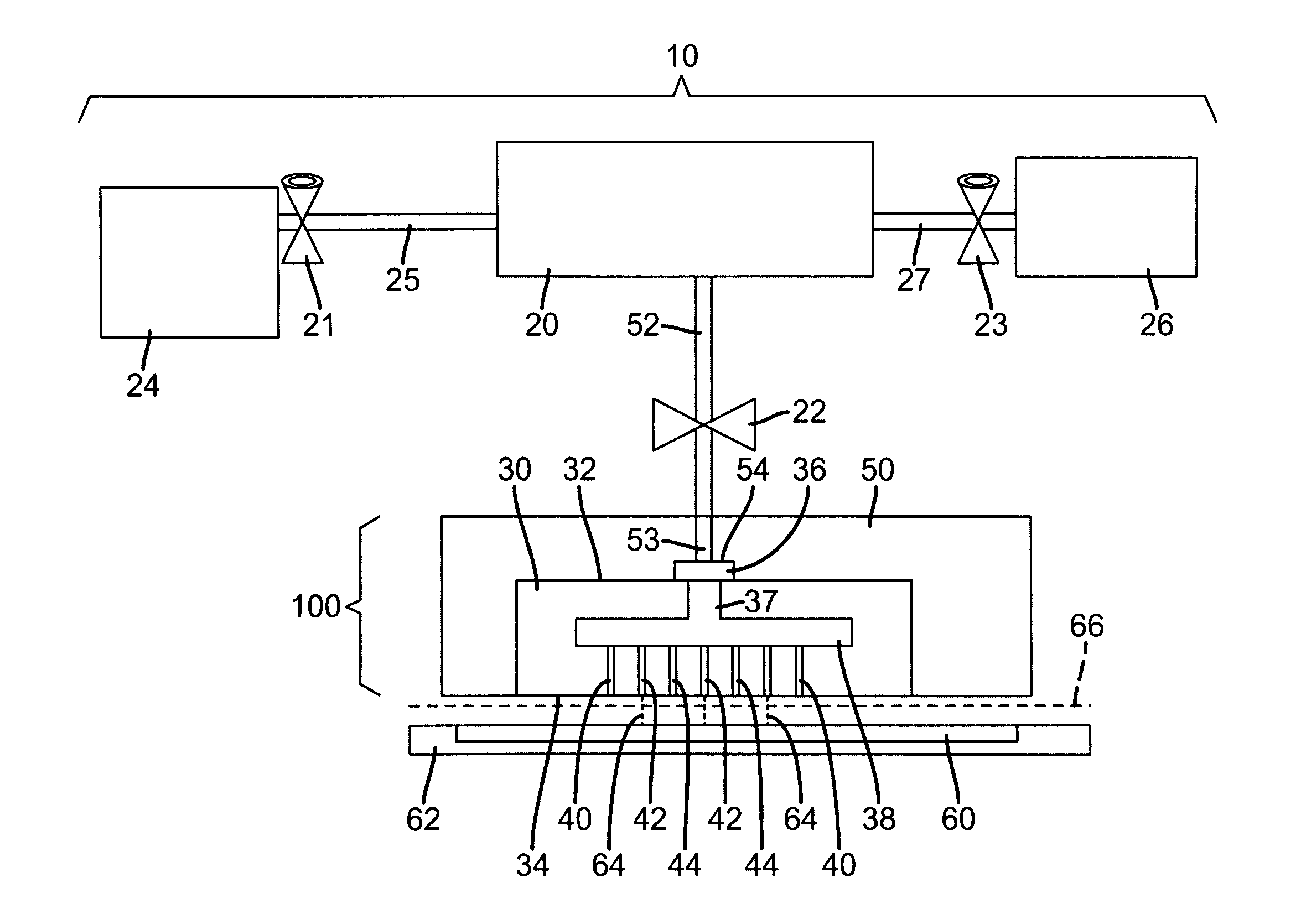
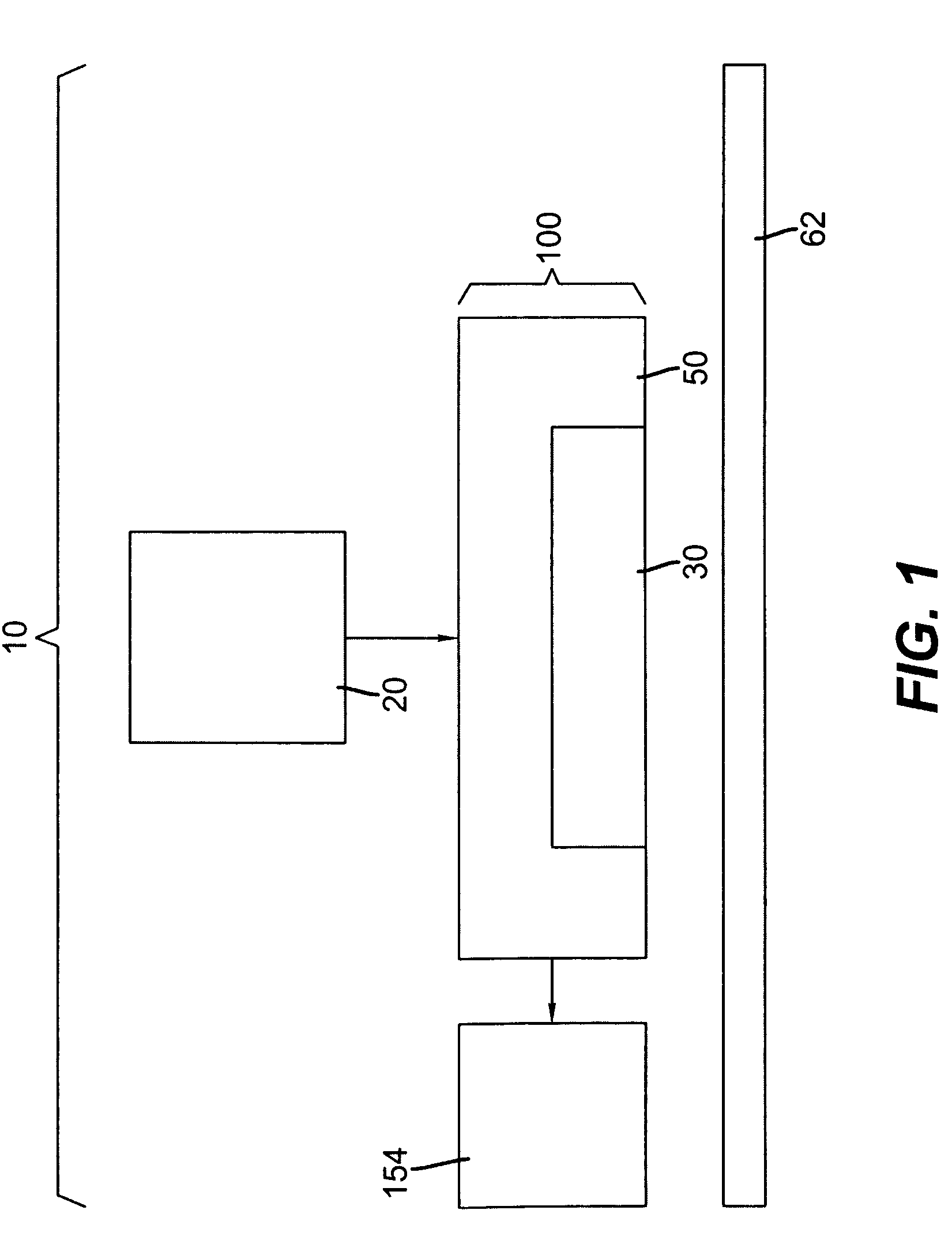
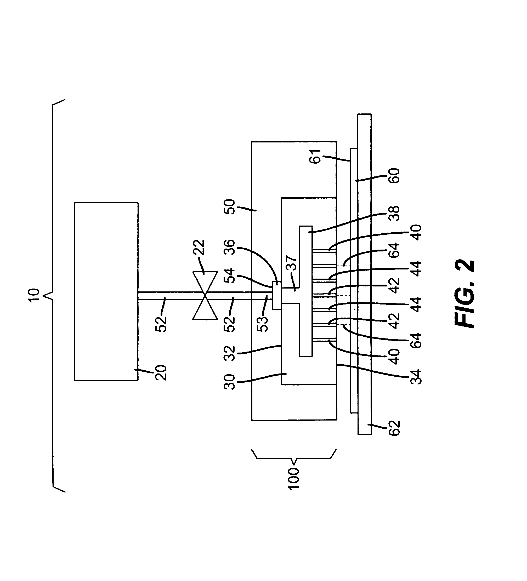
[0068]A 250 ml high-pressure vessel was used as the source of the marking material. The vessel had a floating piston, resistive heaters and a mechanical stirrer to allow operation at desired pressure and temperature. The vessel was connected to the housing with stainless steel tubing that was kept at constant temperature with a circulating water jacket. The silicon side of a 9.9 mm long, 2.5 mm wide, and 1.135 mm thick micro-machined glass-silicon manifold was interfaced with the housing by interposing an In (80%)-Pb (15%)-Ag (5%) gasket that had laser cut holes to mate with conduits in the housing. FIG. 17 shows an optical micrograph of a portion of the micro-machined manifold 30″ used in this example. The micro-machined manifold 30″ shown in the photograph of FIG. 17 is similar to the one shown in FIG. 9 with the exception that there is only one micro-nozzle 40 per fluid chamber 38. The photograph of FIG. 17 was taken with the glass or alternate second piece 43 facing up. All of t...

example 2

[0073]The housing 50 in Example 1 was attached to a different positional control unit that allowed the substrate to move along the x-axis and the housing was now movable—along the y-axis displacing orthogonally back and forth for each new line. Example 1 was then repeated with the following exceptions: (1) Compressed fluid mixture was kept at 125 bar; (2) the substrate 60 was spaced 0.76 mm away from the micro-nozzle outlets 44 at the second surface 43; and (3) the housing 50 and substrate 60 were moved laterally back and forth at a nominal speed of ca. 5.31 m / min. The average line width was ca. 184 μm. (See FIG. 19) which is equivalent to a divergence angle of 3.2 degrees.

example 3

[0074]Example 2 was repeated with the following exceptions: (1) Compressed fluid mixture was kept at 200 bar; and (2) the housing 50 and substrate 60 was moved laterally back and forth at a nominal speed of ca. 15.93 m / min. The average line width was ca. 104 μm which is equivalent to a divergence angle of 0.15 degrees.


PUM


Abstract

A method and apparatus for delivering a mixture of compressed fluid and marking material and depositing the marking material in a pattern onto a substrate, includes a high pressure source of a mixture of compressed fluid and marking material. A micro-machined manifold includes a plurality of micro-nozzles, a fluid chamber, and an entrance port with portions of a first surface of the micro-machined manifold defining the entrance port with the entrance port being connected in fluid communication with the fluid chamber. Each of the micro-nozzles having an inlet and an outlet with the inlet being connected in fluid communication with the fluid chamber and the outlet being located on the second surface of the micro-machined manifold. Each micro-nozzle is shaped to produce a directed beam of the mixture of compressed fluid and marking material beyond the outlet of the micro-nozzle. A housing is connected in fluid communication with the high pressure source and the entrance port of the micro-machined manifold with the connection being a sealed connection. Optionally, a device operable to capture marking material that does not adhere to the substrate can be included.

Description

FIELD OF THE INVENTION[0001]This invention relates generally to printing and more particularly, to printing mixtures of compressed fluids and marking materials through micro-machined components.BACKGROUND OF THE INVENTION[0002]Many marking technologies exist for creating marks or patterns on a substrate. The ink jet printing technology commonly known as “drop-on-demand” provides ink droplets (typically including a dye or a mixture of dyes) for impact upon a recording surface using a pressurization actuator (thermal, piezoelectric, etc.). Selective activation of the actuator causes the formation and ejection of a flying ink droplet that crosses the space between the printhead and the print media and strikes the print media. The formation of printed images is achieved by controlling the individual formation of ink droplets, as is required to create the desired image. Typically, a slight negative pressure within each channel keeps the ink from inadvertently escaping through the nozzle,...

Claims


Application Information

Patent Timeline
Patent Type & Authority Patents(United States)
IPC IPC(8): B41J2/015
CPCB41J2/04B41J2/015
Inventor MEHTA, RAJESH V.MARCUS, MICHAEL A.WANG, RUIZHENGHAWKINS, GILBERT A.
Owner EASTMAN KODAK CO
Why Eureka
Try Eureka