Hydraulic coupling member with electrical bonding contactor

a technology of electrical bonding contactor and hydraulic coupling member, which is applied in the direction of connection contact member material, sealing/packing, and accessories of wells, etc., can solve the problems of consuming anode material, galvanic anode corrode, and insufficient current economic delivery of galvanic anode to provide complete protection

Active Publication Date: 2010-07-27
NAT COUPLING
View PDF53 Cites 21 Cited by
  • Summary
  • Abstract
  • Description
  • Claims
  • Application Information

AI Technical Summary

Problems solved by technology

The galvanic anode continues to corrode, consuming the anode material until eventually it must be replaced.
For larger structures, galvanic anodes cannot economically deliver enough current to provide complete protection.
Electrical bonding is not always assured in an hydraulic coupling.
These devices however, significantly increase the work required to make up and disconnect a hydraulic coupling.
Particularly in the undersea environment where such work must be performed by remotely operated vehicles (ROVs) this is a significant disadvantage.

Method used


Image

  • Hydraulic coupling member with electrical bonding contactor
  • Hydraulic coupling member with electrical bonding contactor
  • Hydraulic coupling member with electrical bonding contactor

Examples


first embodiment

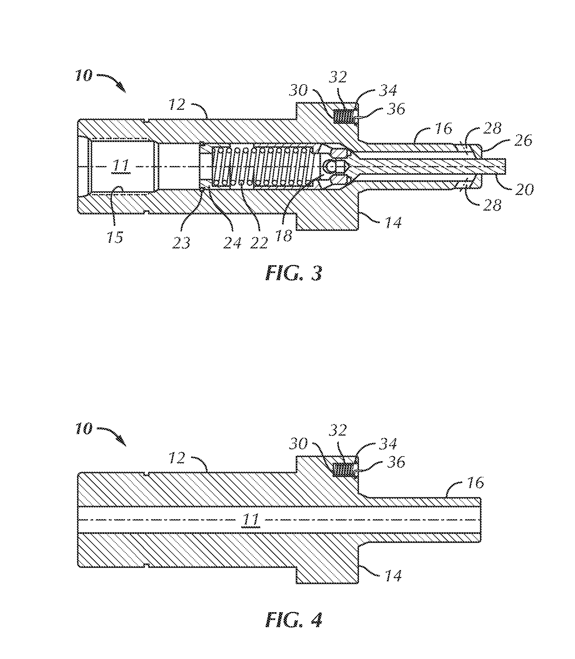
[0054]A male coupling member 10 that has no internal poppet valve is shown in FIG. 4. Bonding device 32 thereof is shown within cavity 30 retained by keeper 34. A coupling of this type benefits particularly from the present invention inasmuch as there are no poppet actuators to contact one another during coupling make up and thereby potentially establish an electrical path through the coupling.

second embodiment

[0055]FIGS. 5 through 8, inclusive, illustrate male coupling members 10 having a bonding device according to the invention. In this embodiment, contactor 40 has a generally cylindrical body with projecting ring 38 and generally conical contact point 37. A first shoulder between projecting ring 38 and the main body portion of contactor 40 contacts keeper 34 to retain contactor 40 in cylindrical cavity 30. Keeper 34 may be a snap ring retained in a groove in the side wall of cavity 30. A second shoulder between projecting ring 38 and the main body portion of contactor 40 bears against resilient member 33 which acts to urge contactor 40 out of cavity 30. In the illustrated embodiment, resilient member 33 is a helically-wound, electrically conductive spring. Resilient member 33 may take other forms—e.g., an elastomeric polymer having a conductive filler. In use, point 37 contacts the leading face of a corresponding female member when the coupling is made up. Contactor 40 retracts into c...


PUM


Abstract

A female hydraulic coupling member and / or a male hydraulic coupling member is equipped with an electrically conductive contactor which contacts the opposing coupling member when the coupling is fully made up thereby electrically bonding the coupling members.

Description

CROSS-REFERENCE TO RELATED APPLICATIONS[0001]NoneSTATEMENT REGARDING FEDERALLY SPONSORED RESEARCH OR DEVELOPMENT[0002]NoneBACKGROUND OF THE INVENTION[0003]1. Field of the Invention[0004]This invention relates to hydraulic couplings. More particularly, it relates to undersea hydraulic couplings used in systems which employ electrical bonding of components.[0005]2. Description of the Related Art[0006]A wide variety of undersea hydraulic couplings are available. Some couplings employ metal seals. Examples of undersea hydraulic couplings having metal seals include U.S. Pat. No. 4,694,859 for “Undersea hydraulic coupling and metal seal” U.S. Pat. No. 4,817,668 for “Integral metal seal for hydraulic coupling” U.S. Pat. No. 4,884,584 for “Internally preloaded metal-to-metal seal hydraulic connector” U.S. Pat. No. 5,029,613 for “Hydraulic coupler with radial metal seal” U.S. Pat. Nos. 5,099,882 and 5,203,374 for “Pressure balanced hydraulic coupling with metal seals” U.S. Pat. No. 5,284,183...

Claims


Application Information

Patent Timeline
Patent Type & Authority Patents(United States)
IPC IPC(8): H01R4/60
CPCF16L25/01F16L1/26Y10T137/87957H01R13/005E21B33/038
Inventor SMITH, III, ROBERT E.
Owner NAT COUPLING
Why Eureka
Try Eureka