Flat tray cartoner

a cartoner and tray technology, applied in the field of cartoning, can solve the problems of unfit cartoners and obstacles in handling, and achieve the effect of facilitating product indexing and turning product entry

Inactive Publication Date: 2010-08-03
R A JONES
View PDF5 Cites 2 Cited by
  • Summary
  • Abstract
  • Description
  • Claims
  • Application Information

AI Technical Summary

Benefits of technology

[0012]A further objective of the invention is to transport an elongated, narrow end leading product into a cartoner station in a relatively straight machine flow vector or direction and to minimize the forces necessary to turn the product to an orientation with a broad side leading in the machine flow direction for transverse insertion into a carton with narrow end leading.
[0015]Preferably, the product buckets each have a leading wall tapered or inclined in rearward direction toward a rearward wall to define a wide bucket mouth and thus facilitate product indexing and turning product entry into the bucket.

Problems solved by technology

A variation in any one of these parameters may render a cartoner unfit for cartoning where one of these parameters differs from that for which the cartoner is designed.
Positive indexing and turning of the trays while maintaining them under positive control presents handling obstacles, particularly at the high flow rates or throughputs desired in excess of 200 trays per minute and preferably at least 240 to 260 trays per minute and up to 300 trays cartoned per minute.

Method used


Image

  • Flat tray cartoner
  • Flat tray cartoner
  • Flat tray cartoner

Examples


Embodiment Construction

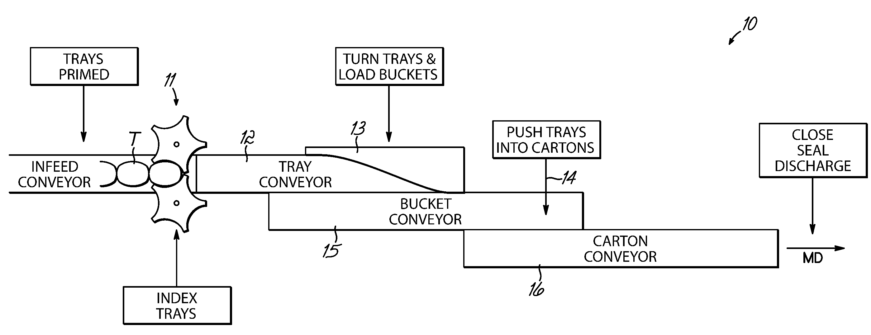
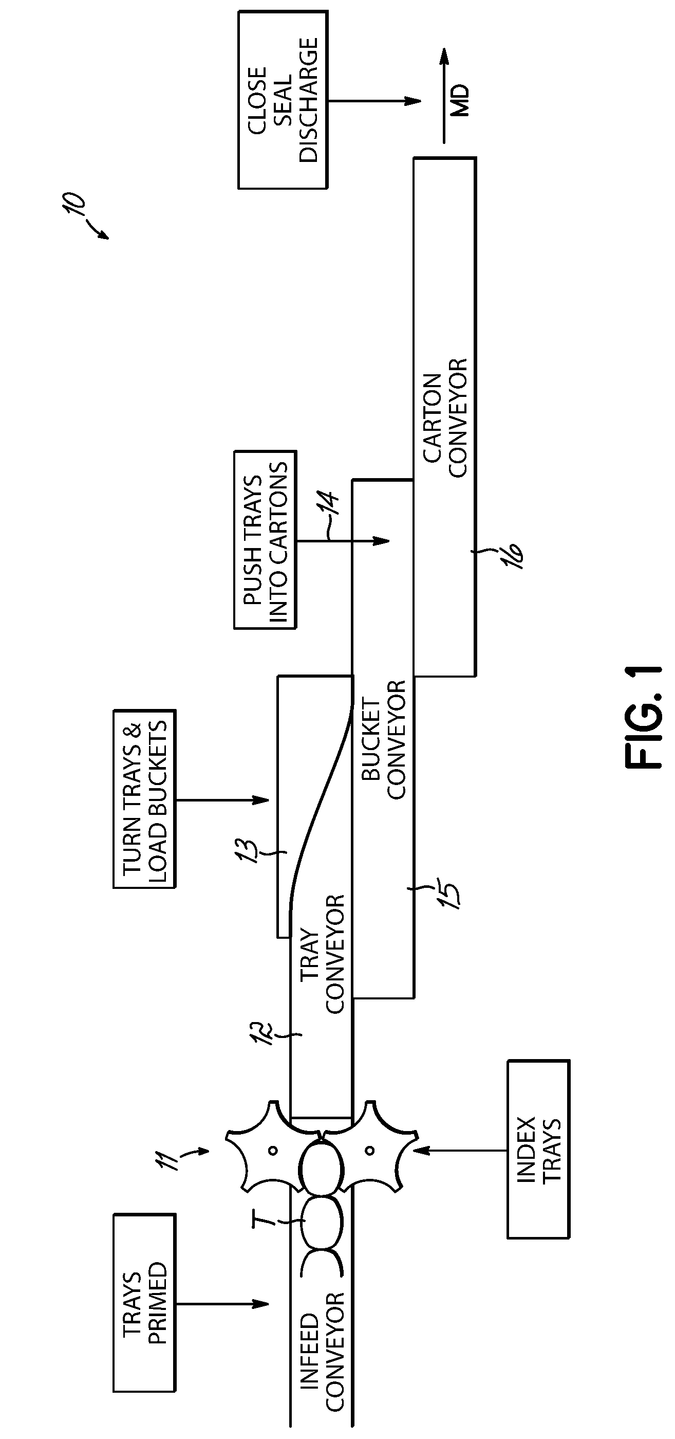
[0045]The overall invention 10 is illustrated in FIG. 1, where trays T are primed on the left end of the figure on a low pressure infeed conveyor. Star wheels 11 both relieve pressure from the “prime” and index trays at predetermined pitch onto a tray conveyor 12. Trays are conveyed in a first direction (machine direction arrow MD) toward a turning guide 13. Guide 13 turns the trays and pushes them in a second direction 14, perpendicular to direction MD, into buckets on a bucket conveyor 15. Trays are conveyed in buckets on conveyor 15 in direction MD from where they are further pushed into open ends of cartons, moving in a direction MD on a carton conveyor 16 adjacent the bucket conveyor 15. The cartons are then closed, sealed and discharged.

[0046]Trays T as described above, may be of somewhat varied shape and size but are preferably relatively flat and are elongated or oblong as shown with opposed narrow ends and elongated edges extending therebetween.

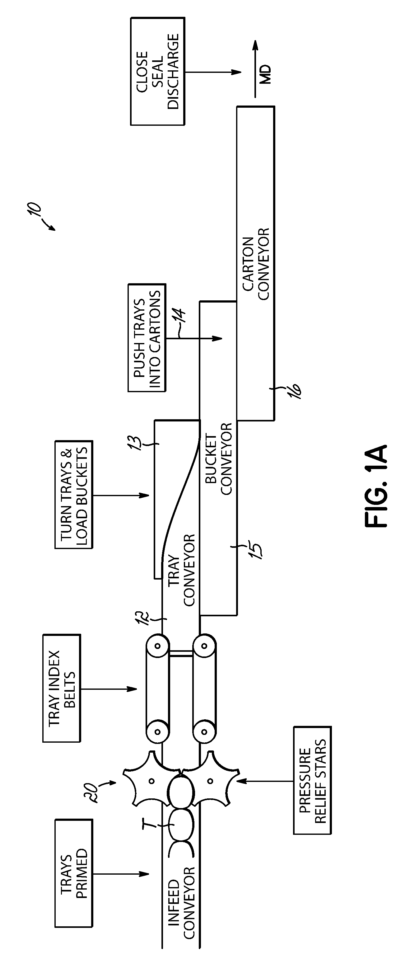
[0047]In an alternate embodim...


PUM

PropertyMeasurementUnit
angleaaaaaaaaaa
pressureaaaaaaaaaa
sizeaaaaaaaaaa

Abstract

Trays are indexed at predetermined pitch on a tray conveyor. As the trays are conveyed, a turning guide engages a leading tray portion, turning the tray and urging it transversely downward and / or into buckets on an adjacent bucket conveyor or cartons on an adjacent carton conveyor. A cam is disposed rearward of each tray on the tray conveyors and the turning trays pivot about that cam. A hold-down prevents trays climbing over the turning guide. Pressure relief and tray indexing are provided upstream of the tray conveyor. Apparatus and methods are disclosed.

Description

FIELD OF THE INVENTION[0001]This invention relates to cartoning and more particularly to apparatus and methods for controlling elongated flat trays containing product as they are conveyed for insertion into a carton.BACKGROUND OF THE INVENTION[0002]The particular parameters of products to be cartoned place a host of varied demands on a cartoner. It is known to feed single or grouped product into buckets in a cartoner and to push the products from the buckets into erected cartons moving alongside the product bucket. However, variations in product delivery orientation, feed rate, flow direction, product size, product shape, packing orientation with respect to the carton parameters and flow or throughput speed all must be considered. A variation in any one of these parameters may render a cartoner unfit for cartoning where one of these parameters differs from that for which the cartoner is designed.[0003]Delivery and insertion of flat trays into cartons presents unique cartoning parame...

Claims


Application Information

Patent Timeline
Patent Type & Authority Patents(United States)
IPC IPC(8): B65G47/24
CPCB65B35/24B65B35/56
Inventor BRUGGER, JEROMELUKES, MATTHEW R.
Owner R A JONES
Why Eureka
Try Eureka