Articulating curved cutter stapler

a cutter and cutter technology, applied in the direction of surgical staples, surgical forceps, paper/cardboard containers, etc., can solve the problem of limiting the potential for reorienting the end effector, and achieve the effect of improving tissue access and ease of us

Active Publication Date: 2010-08-03
ETHICON ENDO SURGERY INC
View PDF33 Cites 1368 Cited by
  • Summary
  • Abstract
  • Description
  • Claims
  • Application Information

AI Technical Summary

Benefits of technology

[0009]It is, therefore, an object of the present invention to provide an articulating surgical stapler having a proximal end and a distal end. The stapler includes a handle at the proximal end and an end effector at the distal end for selective articulation to improve access to tissue requiring treatment and ease of use of the present linear surgical stapler. A support shaft connects the handle to the end effector. An articulation mechanism is positioned between the support shaft and the end effector permitting selective movement of the end effector relative to the support shaft.
[0011]It is a further object of the present invention to provide a surgical stapler including a locking mechanism associated with the ball joint for permitting selective locking of the end effector in a desired orientation and selective release of the end effector for controlled movement when desired.
[0014]It is still another object of the present invention to provide a surgical stapler wherein the ball joint includes a ball with a contoured outer surface shaped and dimensioned to lock with the distal end of the ball lock release tube, the contouring of the ball helping to ensure frictional engagement between the ball and the distal end of the ball lock release tube.
[0026]It is also a further object of the present invention to provide a surgical stapler wherein the push collar is selectively released from engagement with the cartridge housing permitting continued forward movement of the push collar in a manner forcing a knife and staples with the cartridge housing toward the anvil.
[0027]It is also an object of the present invention to provide a surgical stapler further including an anti-back up mechanism preventing undesired rearward movement of the cartridge housing.

Problems solved by technology

This, however, limits the potential for reorienting the end effector as orientation thereof is limited by the access opening through which the surgical stapling and cutting instrument is inserted within the body.

Method used


Image

  • Articulating curved cutter stapler
  • Articulating curved cutter stapler
  • Articulating curved cutter stapler

Examples


Embodiment Construction

[0042]The detailed embodiments of the present invention are disclosed herein. It should be understood, however, that the disclosed embodiments are merely exemplary of the invention, which may be embodied in various forms. Therefore, the details disclosed herein are not to be interpreted as limiting, but merely as the basis for the claims and for teaching one skilled in the art how to make and / or use the invention.

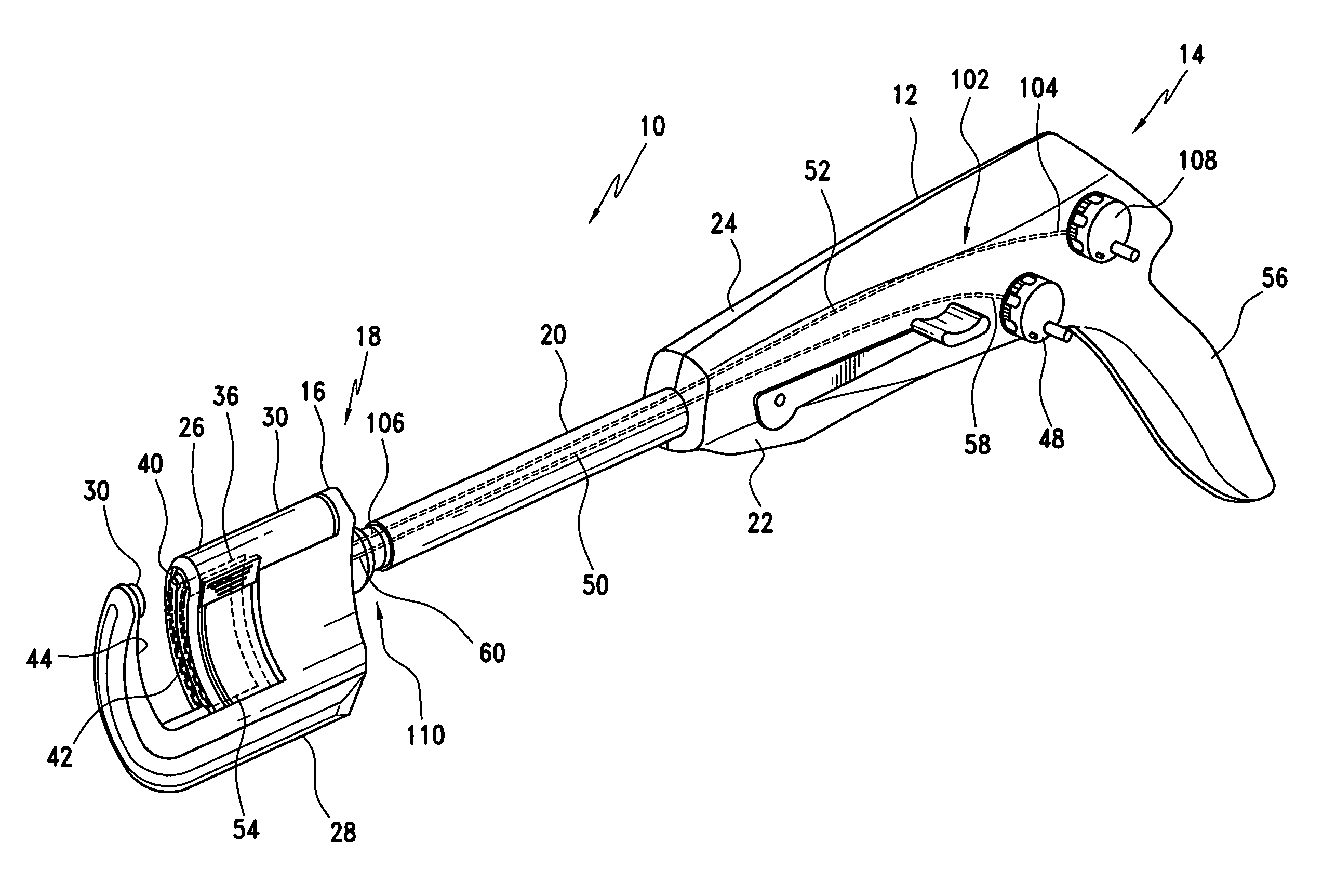
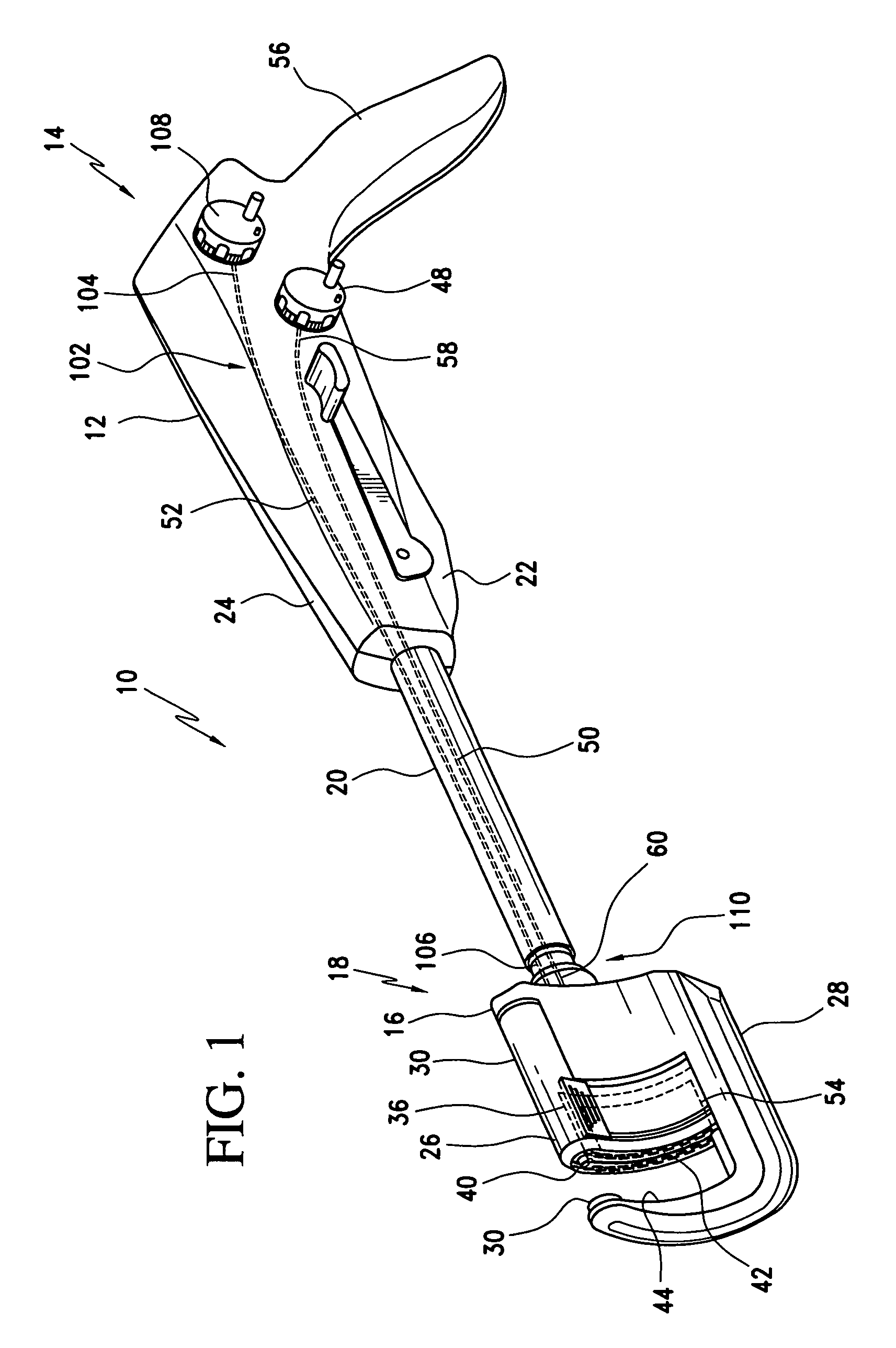
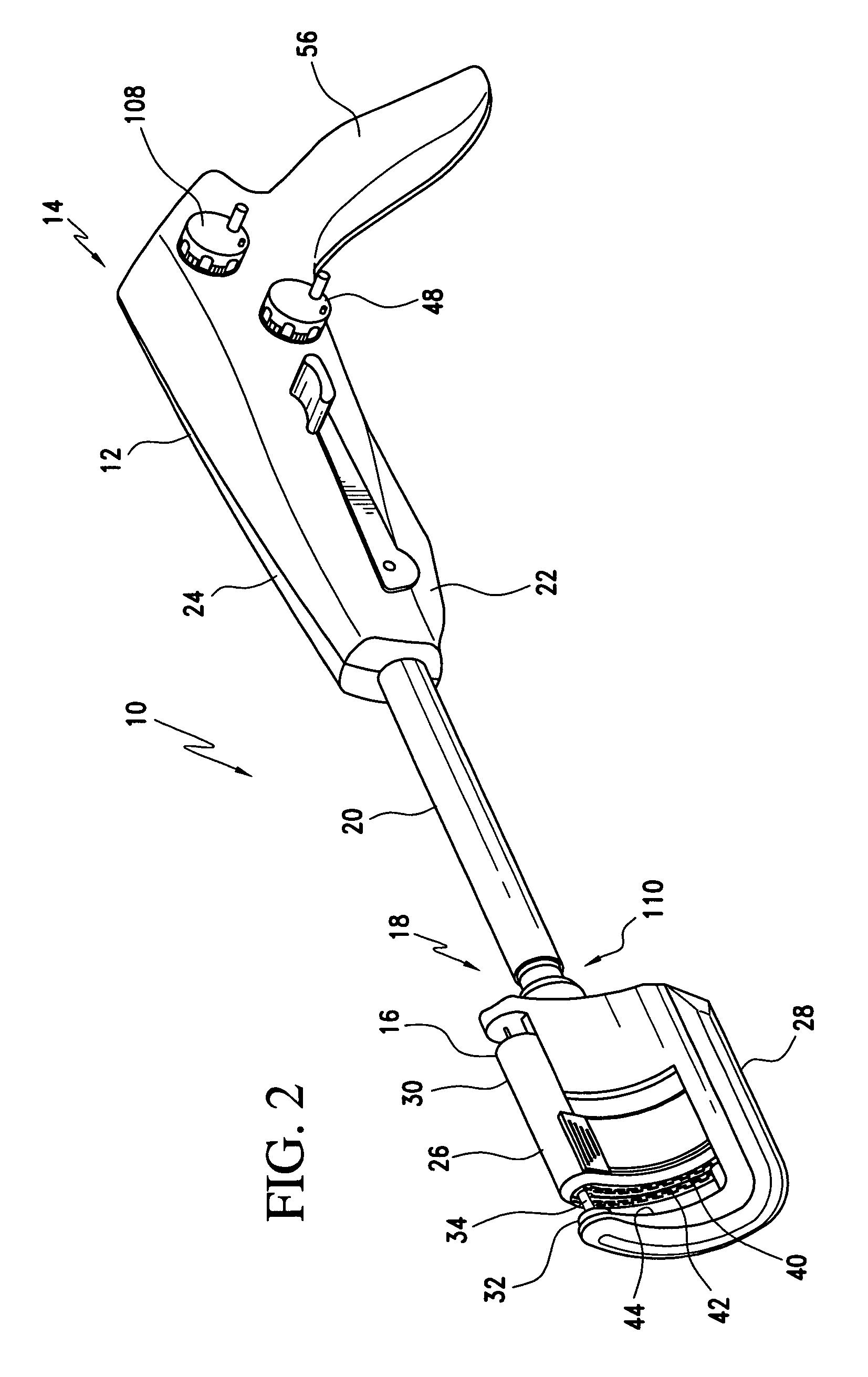
[0043]Referring to FIGS. 1 to 10, a surgical stapling and cutting instrument, in particular, a linear surgical stapler, 10 is disclosed. The linear surgical stapler 10 is designed to staple and cut tissue. The linear surgical stapler 10 has a handle 12 at a proximal end 14 and an end effector 16 at an opposite distal end 18. As is discussed below in substantial detail, the end effector 16 is supported such that it may be selectively articulated to improve access to tissue requiring treatment and ease of use of the present linear surgical stapler 10.

[0044]The end effector 16...


PUM

PropertyMeasurementUnit
lengthaaaaaaaaaa
movementaaaaaaaaaa
flexibleaaaaaaaaaa

Abstract

An articulating surgical stapler having a proximal end and a distal end includes a handle at the proximal end and an end effector at the distal end for selective articulation to improve access to tissue requiring treatment and ease of use of the present linear surgical stapler. A support shaft connects the handle to the end effector. An articulation mechanism is positioned between the support shaft and the end effector permitting selective movement of the end effector relative to the support shaft.

Description

CROSS REFERENCE TO RELATED APPLICATIONS[0001]This application is a continuation-in-part of U.S. patent application Ser. No. 11 / 014,910, filed Dec. 20, 2004, entitled “CURVED CUTTER STAPLER SHAPED FOR MALE PELVIS”, which is currently pending, which claims priority of U.S. Provisional Application Ser. No. 60 / 532,912, entitled “CURVED CUTTER STAPLER SHAPED FOR MALE PELVIS”, filed Dec. 30, 2003.BACKGROUND OF THE INVENTION[0002]1. Field of the Invention[0003]The present invention relates to a surgical stapling and cutting instrument adapted for use in the diagnosis and therapy of pathologies treated by stapled resection. More particularly, the present invention relates to a surgical stapling and cutting instrument offering articulation of the end effector permitting improved access to surgical sites.[0004]2. Description of the Prior Art[0005]Surgical stapling and cutting instruments are commonly utilized in the diagnosis and treatment of pathologies treated by staple resection. Surgical ...

Claims


Application Information

Patent Timeline
Patent Type & Authority Patents(United States)
IPC IPC(8): A61B17/068F16D11/06F16C11/06A61B17/04A61B17/10
CPCA61B17/072A61B2017/00473A61B2017/0688A61B2017/07221A61B2017/2927Y10T403/32024A61B2017/2943A61B2017/320052Y10T403/32311Y10T403/32032A61B2017/2929A61B17/068A61B17/115A61B17/122A61B17/04
Inventor MATHER, MICHAEL T.KRUSZYNSKI, MICHAEL L.SCHWEMBERGER, RICHARD F.PARKER, MICHAEL A.
Owner ETHICON ENDO SURGERY INC
Why Eureka
Try Eureka