Muscle training apparatus and method

a technology of muscle training and muscle training, applied in the field of muscle trainer and muscle training method, can solve the problems of undesirable dominant muscle condition and its attendant disadvantages

Inactive Publication Date: 2010-08-03
PRIESTER WILLIAM B +1
View PDF35 Cites 40 Cited by
  • Summary
  • Abstract
  • Description
  • Claims
  • Application Information

AI Technical Summary

Benefits of technology

[0017]To better represent the movement of the entire golf club in space, the position of the club face will hereinafter be referred to as the club face plane. Regardless of the loft of the club face, the club face plane represents the position of the club face as if the club face had zero degrees of loft. Unlike the club shaft plane which typically has some degree of curvature, the club face plane is a true plane since it is an extension of the zero degree club face. The concepts of the club face plane and the club shaft plane help one to visualize the relationship between the movement of the club face and the club shaft during the golf swing. The proper relationship between these two planes is captured in a “two-plane-merger” golf swing theory.
[0041]The method contemplated by this invention includes the steps of swinging a golf club or a golf club simulator with the hinge motion normally generated by the golfer, determining whether the actual hinge motion is different from the ideal hinge motion due to the non-dominating hinge muscle allowing the dominating hinge muscle to hinge the club in a dominating hinge force direction away from the ideal hinge motion, applying an external force to the golf club simulator independently of any force applied by the golfer to further urge the simulator in the dominating hinge direction, and using the non-dominating hinge muscle to hinge the golf club simulator against the external force in the non-dominating hinge direction toward ideal hinge motion, thereby exercising the non-dominating hinge muscle in a more strenuous fashion than the dominating hinge muscle to eventually provide balanced muscle strength of the two muscles.

Problems solved by technology

This undesirable dominant-muscle condition and its attendant disadvantages are particularly apparent in sporting games such as, for example, the game of golf, where the implement is a golf club and the individual is a golfer.
However, the ideal club shaft path does not typically coincide with a true plane like a sheet of glass.

Method used


Image

  • Muscle training apparatus and method
  • Muscle training apparatus and method
  • Muscle training apparatus and method

Examples


first embodiment

[0100]As shown in FIGS. 4 and 5, the muscle trainer 44 of the invention includes a hollow shaft 54 having a flat motor-mount pad 56 formed at a distal end of the shaft, and a grip 58 attached to an outer side of the shaft adjacent a proximal end thereof. The grip 58 is formed from a soft non-metallic material, such as, for example, leather, of the type typically used to form the grip of a conventional golf club, such as, for example, the club 32 (FIG. 1).

[0101]Referring to FIGS. 4 and 5, the muscle trainer 44 further includes an electric motor 60 having a rotatable drive shaft 62 extending from one end of a motor housing 64. One end of the motor housing 64 is placed against a first side 66 of the pad 56, and is attached to the pad, such as by screws 67. The drive shaft 62 extends through an opening 69 formed through the pad 56 to a second side 68 of the pad.

[0102]The motor 60 could be of the type typically used to power radio-controlled miniature models such as, for example, model a...

second embodiment

[0127]As shown in FIG. 10, the muscle trainer 104, which is the invention, includes a hollow shaft 106. The muscle trainer 104 differs from the muscle trainer 44 (FIG. 4) in that the length of the shaft 106 is shorter than the length of the shaft 54. Otherwise the muscle trainers 44 and 104 are substantially identical. Except for the shaft 106, the elements of the muscle trainer 104 are identified in FIG. 10 by the same numbers as the corresponding elements of the muscle trainer 44 shown in FIG. 4.

[0128]In the motor-mounted arrangement of the muscle trainer 104 illustrated in FIG. 10, a common axis of the motor 60 and the blades 72 extends at an angle of ninety degrees from the shaft 54 in the same manner as in the motor-mounted arrangement of the muscle trainer 44.

[0129]The muscle trainer104 is preferably used in the same manner as the muscle trainer 44, as described above. The shorter shaft 106 allows the muscle trainer 104 to be used in a closer-quarters environment, such as, for...

third embodiment

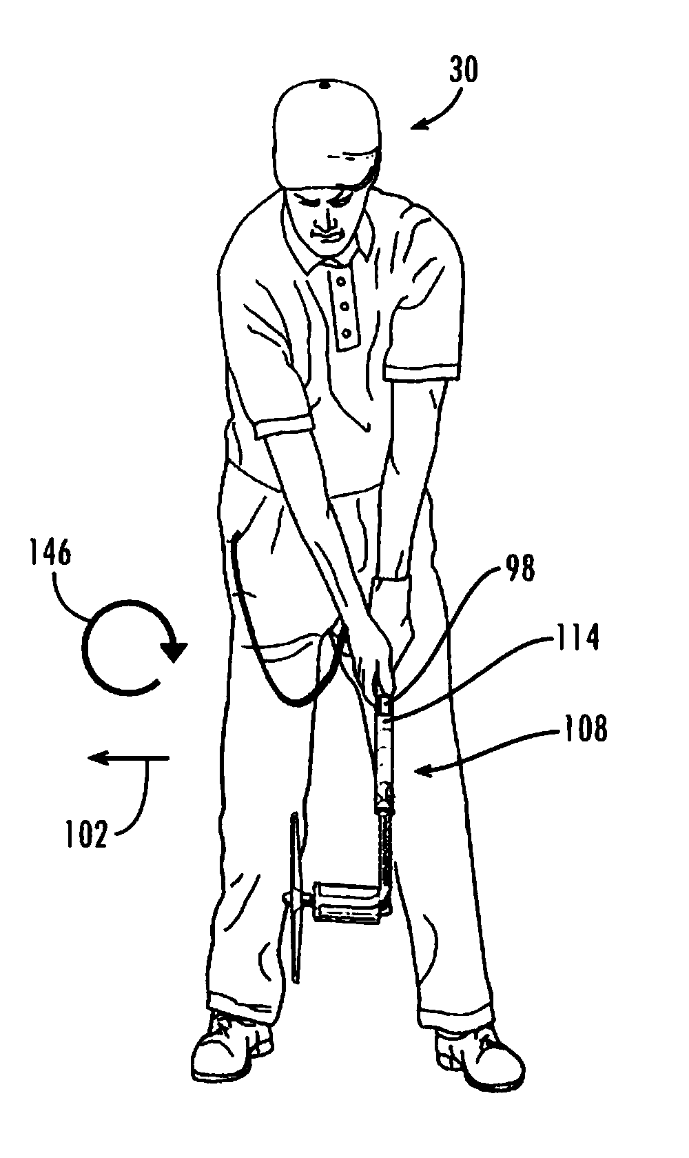
[0131]With that in mind, as shown in FIGS. 12 and 13, the muscle trainer 108 is the invention. The muscle trainer 108 includes a hollow shaft 110 having a flat motor-mount pad 112 formed at a distal end of the shaft, and a grip 114 attached to an outer side of the shaft adjacent a proximal end thereof. The grip 114 is formed from a soft non-metallic material, such as, for example, leather, of the type typically used to form the grip of a conventional golf club, such as, for example, the club 32.

[0132]The shaft 110 is formed with a first straight section 116 which includes the grip 114, and a second straight section 118 which extends at an angle of substantially ninety degrees from the section 116 at a juncture 120 of the first and second straight sections. The shaft 110 is further formed with a third straight section 122, which extends at an angle of substantially ninety degrees from the second straight section 118 at a juncture 124 of the second and third straight sections. The fir...


PUM


Abstract

The invention is directed to a muscle trainer for exercising opposing muscles of a person moving an implement, such as a golf club, wherein, if the opposing muscles were of appropriate strength, the opposing muscles would desirably apply forces in opposite directions to the implement to assist in maintaining an ideal movement of the implement. The contemplated muscle trainer of this invention includes a body and a force generator positioned at a prescribed location on the body for urging the body in a direction away from a force direction which a weaker set of the opposing muscles would normally apply to the implement in the movement of the implement by the person.

Description

[0001]This application claims priority as a continuation-in-part to copending U.S. patent application Ser. No. 10 / 681,971 filed Oct. 9, 2003 now U.S. Pat. No. 7,351,157 titled “Muscle Training Apparatus Method,” the entire contents of which are incorporated herein by reference.FIELD[0002]This invention relates to a muscle trainer and to methods of exercising a muscle. This invention particularly relates to a muscle trainer for use by an individual when exercising one or more muscles used to swing an implement, and / or when exercising one or more muscles used to rotate the implement, and to methods of exercising such muscles.BACKGROUND OF THE INVENTION[0003]Many types of activities require an individual to swing an implement in an attempt to successfully accomplish the end goal of participation in such activity. For example, when participating in any of several sporting games, an individual may be required to swing any of several different implements, each of which is unique to a part...

Claims


Application Information

Patent Timeline
Patent Type & Authority Patents(United States)
IPC IPC(8): A63B69/36
CPCA63B69/3623A63B69/3632A63B69/3608A63B21/0085A63B21/0088A63B2225/09A63B2069/0008A63B15/00A63B69/38
Inventor PRIESTER, WILLIAM B.MAY, RICHARD E.
Owner PRIESTER WILLIAM B
Why Eureka
Try Eureka