Overhead pull-out swing-down drawer

Inactive Publication Date: 2010-08-10
SIMAITIS VAIDOTAS JOSEPH
View PDF44 Cites 45 Cited by
  • Summary
  • Abstract
  • Description
  • Claims
  • Application Information

AI Technical Summary

Benefits of technology

[0010]Without some assistance, the rotation from 90° up to 90° down would be a very difficult motion to control, because of the weight of the drawer, its contents, and the door. It would be extremely difficult to push the drawer back up. An embodiment of this invention solves this difficulty with the use of extension springs to help pull the drawer closed. The choice of extension springs and the location of the spring attachment points

Problems solved by technology

There are two problems with parallelograms when the 4 pivot axes are all in one plane.
The most severe problem occurs at that point where the parallelogram becomes undefined (i.e., the angles inside the parallelogram are at zero degrees so that it is in fact a line as opposed to a parallelo

Method used


Image

  • Overhead pull-out swing-down drawer
  • Overhead pull-out swing-down drawer
  • Overhead pull-out swing-down drawer

Examples


Embodiment Construction

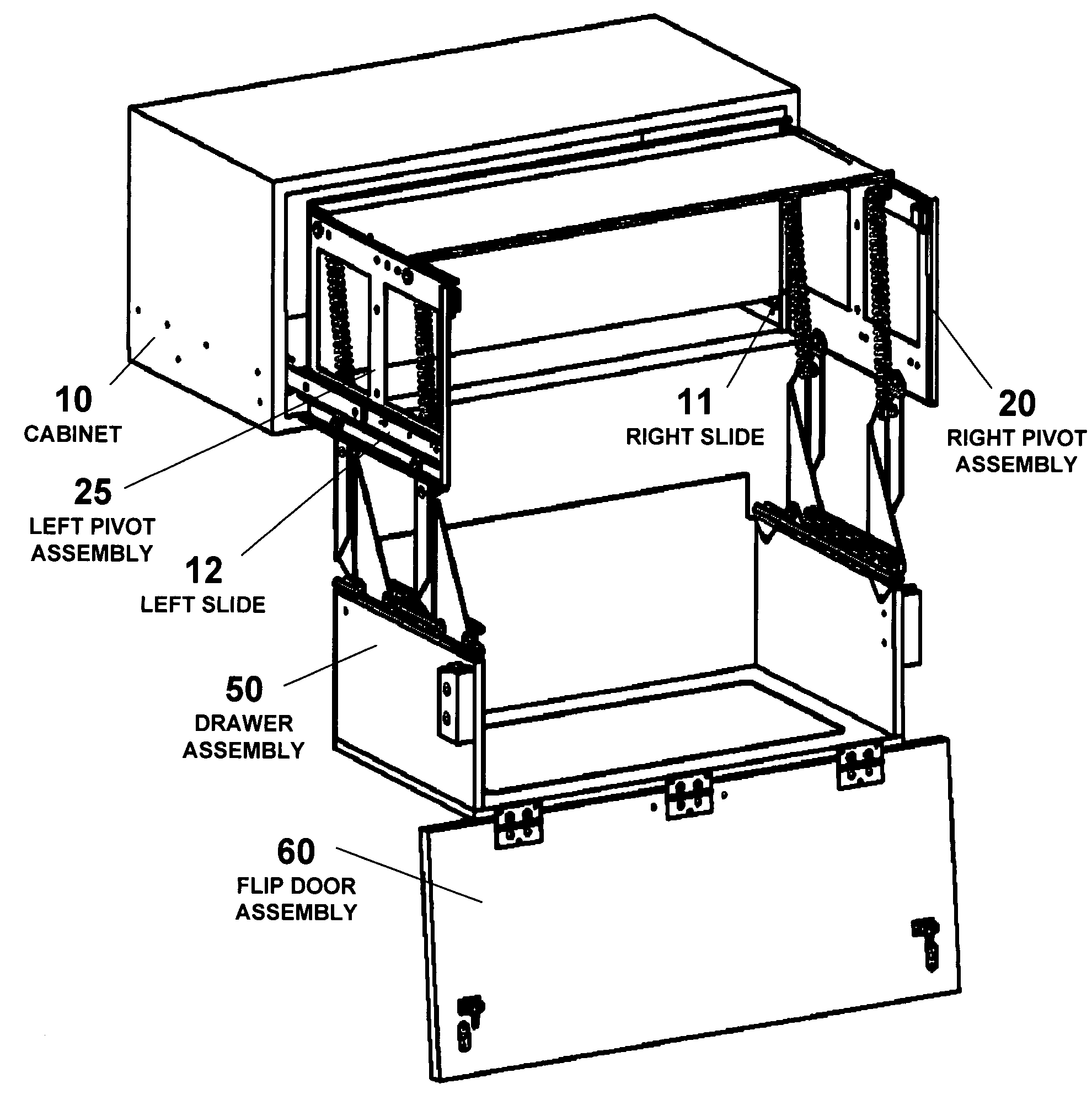
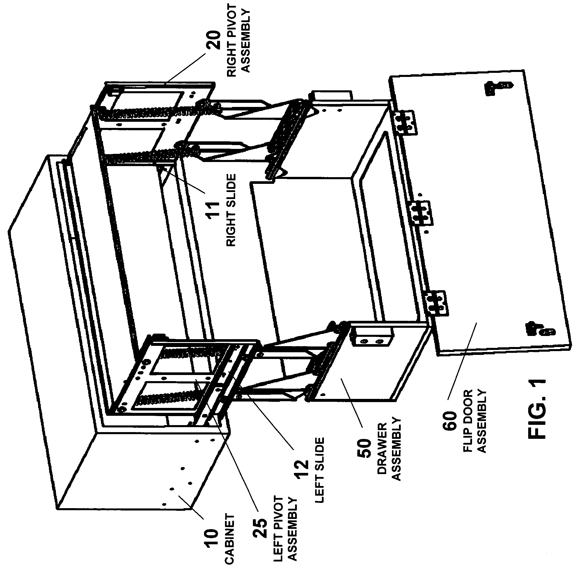
[0029]As shown in FIG. 1, a conventional kitchen cabinet 10 usually composed of wood can be mounted above existing wall cabinets. Commercial drawer slides, right slide 11 and left slide 12, are attached to both inside sides of the cabinet 10. The slides are preferably ones with provisions for over-travel when extended. A slide catch (81, as shown in FIG. 2) may be used on the end of each slide (right slide 11 and left slide 12) to stop the drawer assembly 50 from traveling beyond a desired length as the drawer assembly 50 slides out of the cabinet 10. Right pivot assembly 20 attaches to the inside of right slide 11. The left pivot assembly 25 attaches to the inside of left slide 12. The drawer assembly 50 is then attached to the pivot assemblies 20 and 25, and flip door assembly 60 in turn is attached to drawer assembly 50. FIG. 1 shows the drawer in the swing-down position with the door flipped open.

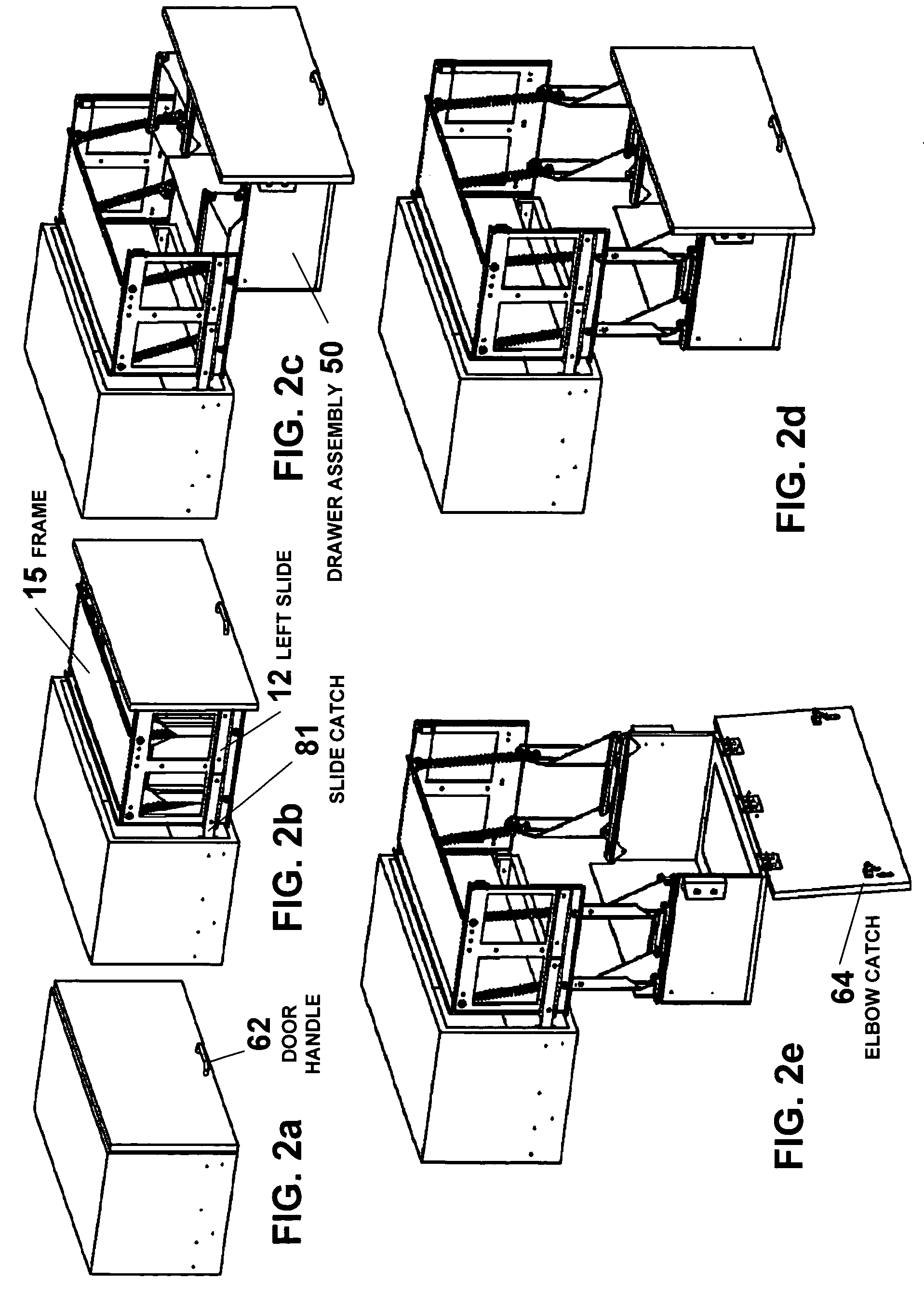
[0030]FIG. 2a through FIG. 2e clockwise from upper left illustrates the sequence of...


PUM


Abstract

A pivot assembly that can be inserted into kitchen cabinets to utilize otherwise unused and unreachable overhead spaces over kitchen wall cabinets. The pivot assembly has a pair of pivot arms pivotally connected to opposite sides of a frame, the frame slidably attached within a cabinet. A drawer is connected to the pivot assembly between the pivot arms. The drawer slides out of the cabinet on a pair of drawer slides and rotates down and out 180 degrees on the pivot arms, from an up position to a down position, wherein the drawer remains stable even as the pivot arms pass through a middle position. The pivot arms form a primary and secondary parallelogram shape during operation, the secondary parallelogram supporting the primary parallelogram at its weakest point in the middle position.

Description

BACKGROUND OF THE INVENTION[0001]The present invention provides a way to utilize otherwise unreachable overhead spaces, especially in kitchen cabinetry, where the wall cabinets often end at about 7 feet, and the ceiling is at 8 feet or more. These spaces are often occupied by soffits, or are left open.[0002]By installing new open-faced cabinets in these spaces, the mechanism embodied in this invention can be inserted with an appropriate drawer and front door or drawer front. The cabinets and door or front can match the already existing cabinetry.[0003]The invention can also be used without a front door, where there are very tall cabinets already in place, and where the top shelf is too high to reach easily. In this situation, the top shelf can be replaced by the swing-down open front drawer, which is normally hidden by the existing cabinet doors.[0004]The solution to this task is identified by the features declared in the claims.[0005]Additionally, the invention can be utilized beyo...

Claims


Application Information

Patent Timeline
IPC IPC(8): A47B67/02A47F5/08
CPCA47B46/005A47B51/00
Inventor SIMAITIS, VAIDOTAS JOSEPH
Owner SIMAITIS VAIDOTAS JOSEPH
Why Eureka
Try Eureka