Method for simulating deformation of rubber compound with filler particles

a technology of rubber compound and filler particles, which is applied in the field of computerized methods for simulating deformation of rubber compound with filler particles, can solve the problems of weak large deformation calculation, inability to continue deformation calculation, and increased deformation of elements eb>1/b>, so as to achieve large deformation calculation, increase the degree of deformation freedom of node points of elements of pseudo-two-dimensional rubber compound models, and easy formation

Active Publication Date: 2016-05-24
SUMITOMO RUBBER IND LTD
View PDF17 Cites 0 Cited by
  • Summary
  • Abstract
  • Description
  • Claims
  • Application Information

AI Technical Summary

Benefits of technology

[0012]It is therefore, an object of the present invention to provide a method for simulating deformation of a rubber compound with filler particles, in which a pseudo-two-dimensional rubber compound model is used, and thereby a large deformation calculation is possible without increasing the rubber compound model generation time.
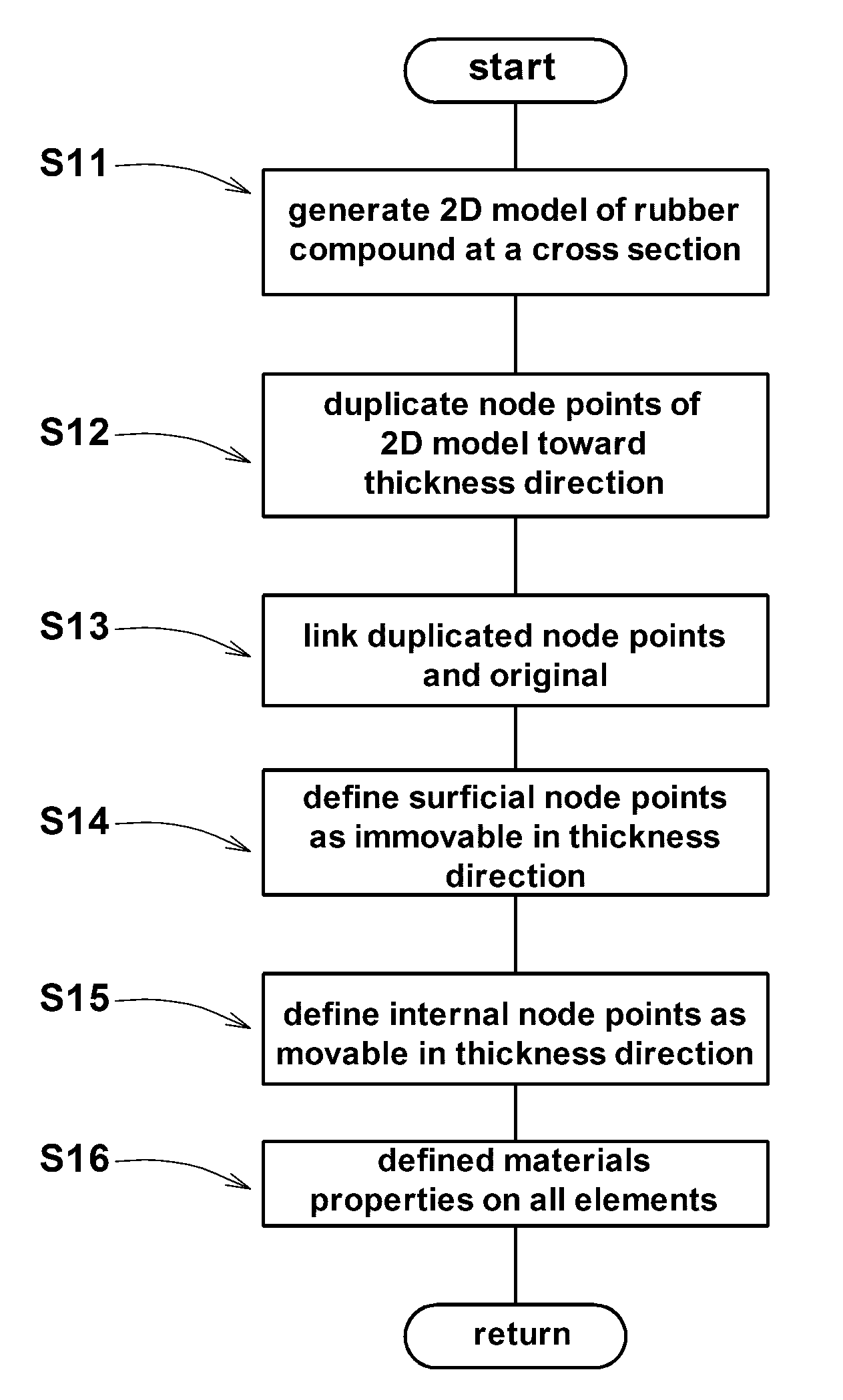
[0024]Therefore, the degree of deformation freedom of node points of elements of the pseudo-two-dimensional rubber compound model becomes increased when compared with a two-dimensional rubber compound model, therefore, it is possible to make a large deformation calculation.
[0025]Further, since the pseudo-two-dimensional rubber compound model has the same cross section in the thickness direction, it can be formed easily by duplicating a two-dimensional model. Therefore, its generation time can be remarkably shortened when compared with a three-dimensional model.
[0026]Thus, in the method according to the present invention, a large deformation calculation is possible and the rubber compound model generation time can be shortened.

Problems solved by technology

Particularly, since the deformation freedom is less in the two-dimensional rubber compound model a1, with the progress of deformation, the strain of the elements e1 is increased, and often it becomes impossible to continue the deformation calculation.
As explained, in comparison with the three-dimension simulation method, the two-dimensional simulation method has the merit of shorter model generation time, but it is weak in large deformation calculation.

Method used


Image

  • Method for simulating deformation of rubber compound with filler particles
  • Method for simulating deformation of rubber compound with filler particles
  • Method for simulating deformation of rubber compound with filler particles

Examples


Embodiment Construction

[0035]Embodiments of the present invention will now be described in detail in conjunction with accompanying drawings.

[0036]The present invention is directed to a computerized method for simulating deformation of a rubber compound. The rubber compound as the analysis object comprises a rubber component as the rubber matrix and filler particles dispersed in the rubber matrix. The rubber component can be, for example, natural rubber (NR), isoprene rubber (IR), butyl rubber (IIR), butadiene rubber (BR), styrene butadiene rubber (SBR), styrene isoprene butadiene rubber (SIBR), ethylene-propylene-diene rubber (EPDM), chloroprene rubber (CR), acrylonitrile butadiene rubber (NBR) and the like. The filler can be carbon black, silica, clay, talc, magnesium carbonate, magnesium hydroxide and the like. Of course the rubber component and filler are not limited to these examples. Further, various additives, e.g. sulfur, vulcanization accelerator and the like may be added in the rubber compound,

[0...


PUM


Abstract

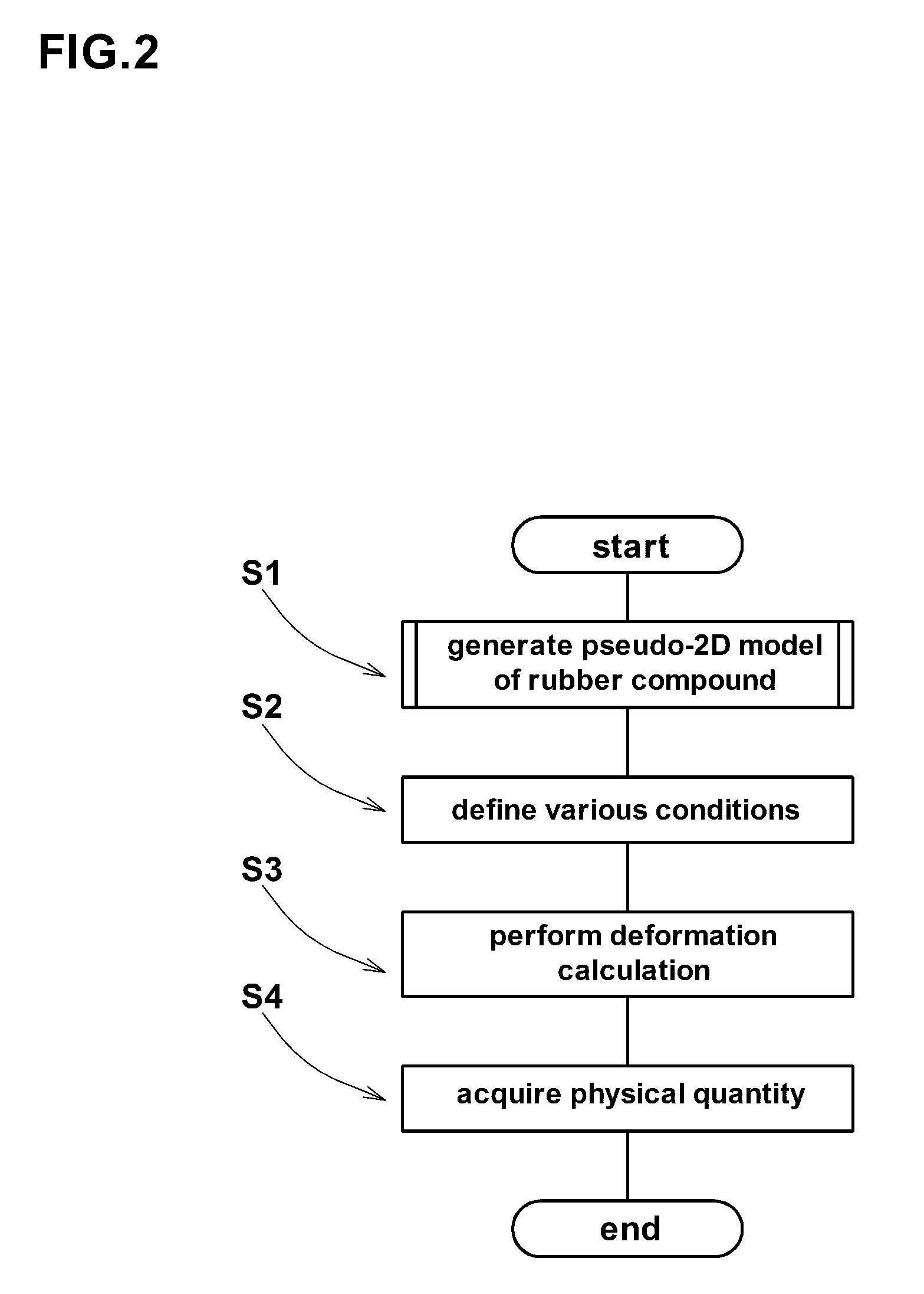
A computerized method for simulating deformation of a rubber compound with filler particles comprises: a step in which a pseudo-two-dimensional rubber compound model of the rubber compound is generated; a step in which a deformation calculation is performed by the use of the pseudo-two-dimensional rubber compound model; and a step in which a necessary physical quantity is acquired from the deformation calculation. The pseudo-two-dimensional rubber compound model comprises a model of a rubber matrix and a plurality of models of filler particles. The pseudo-two-dimensional rubber compound model has a small thickness and has the same cross section in succession in the thickness direction.

Description

BACKGROUND OF THE INVENTION[0001]The present invention relates to a computerized method for simulating deformation of a rubber compound with filler particles, more particularly to a method using a pseudo-two-dimensional rubber compound model capable of calculating a large deformation without increasing the model generation time.[0002]In order to save time and cost for making prototypes of a rubber product made of a rubber compound, the use of a computer simulation for analyzing deformation of the rubber compound becomes popular in recent years.[0003]Such simulation methods are disclosed in for example Japanese Patent Application Publication Nos. JP-A-2005-121535, JP-A-2005-146146, JP-A-2006-193560, JP-A-2008-122154, JP-A-2009-216612, JP-A-2009-276147, JP-A-2009-282569, JP-A-2010-205165, and JP-A-2010-49414.[0004]Generally, the simulation methods are classified into a two-dimensional simulation method and a three-dimensional simulation method.[0005]In a two-dimensional simulation met...

Claims


Application Information

Patent Timeline
Patent Type & Authority Patents(United States)
IPC IPC(8): G06F17/50G06F7/60G06F7/48
CPCG06F17/5018G06F30/23
Inventor NAITO, MASATO
Owner SUMITOMO RUBBER IND LTD
Why Eureka
Try Eureka