

Multi-row block supporting row level redundancy in a PLD
- Summary
- Abstract
- Description
- Claims
- Application Information
AI Technical Summary
Benefits of technology
Problems solved by technology
Method used
Image

Examples
Embodiment Construction
[0033]The present invention will now be described in detail with reference to a various embodiments thereof as illustrated in the accompanying drawings. In the following description, specific details are set forth in order to provide a thorough understanding of the present invention. It will be apparent, however, to one skilled in the art, that the present invention may be practiced without using some of the implementation details set forth herein. It should also be understood that well known operations have not been described in detail in order to not unnecessarily obscure the present invention. Further, it should be noted that the techniques of the present invention could be applied to a variety of systems or electronic devices such as programmable devices and application-specific integrated circuit (ASIC) devices.
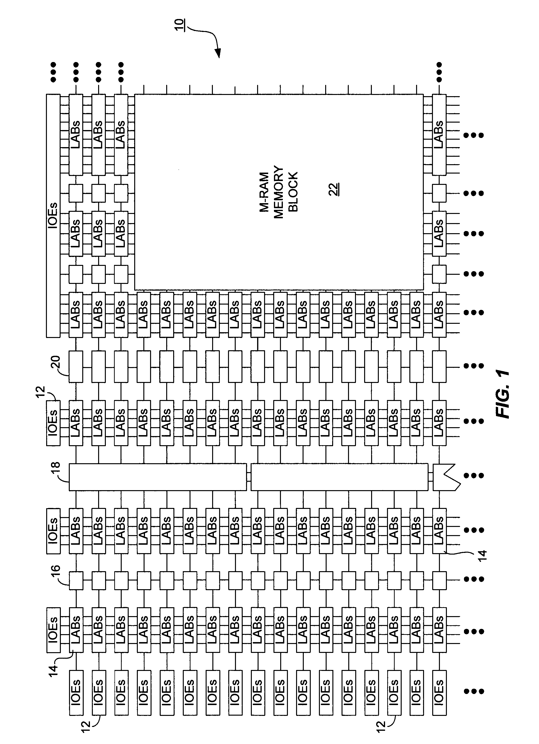
[0034]FIG. 1 shows an example of a block diagram of a Programmable Logic Device (PLD). The PLD 10 includes a two dimensional row and column based architecture including ...
PUM
 Abstract
Description
Claims
Application Information