Elongated edging assembly

a technology of edging and assembly, which is applied in the direction of paving gutters/kerbs, horticulture, etc., can solve the problems of lack of vertical flexibility, difficult installation of many prior art devices, and occasional gaps between ground and strip

Active Publication Date: 2010-08-17
BRAVO FOXTROT HLDG
View PDF37 Cites 15 Cited by
  • Summary
  • Abstract
  • Description
  • Claims
  • Application Information

AI Technical Summary

Problems solved by technology

Many of these prior art devices are difficult to install and sometimes require the digging of trenches for installation.
Moreover, such retaining strips, while sometimes bendable in a horizontal plane perpendicular to the ground, often lack the vertical flexibility needed to conform to changes in ground slope while maintaining a perpendicular relationship between the ground surface and the retaining strip barrier.
And even when such joints are used, the inability of a given strip to conform to changes in ground slope will result in occasional gaps between the ground and the strip.
These prior art devices also generally are susceptible to a serious problem of tending to pull up out of the ground, particularly when the ground is subject to heaving by freezing or changes in moisture content.
Many of the prior devices consist of relatively complicated assemblies such that the precise alignment and overlap of a relatively large number of segments is unnecessarily complicated, time-consuming, and tedious.
However, flat vertical wall restraining strips of the past that have adequate mechanical strength to withstand this lateral force are generally not sufficiently flexible to allow the same to conform easily to changes in ground slope.
Another problem with prior art edging devices is that for practical reasons the same must be made in smaller lengths and must therefore be connected together usually at the job site.
Present day connectors are often deficient and incapable of totally resisting the multitude of forces which are imposed on the devices during installation and use.
That is to say, while a given device might be capable of resisting forces or twisting imposed in one direction, the same device might be incapable of resisting forces or twisting imposed in a different direction.

Method used


Image

  • Elongated edging assembly
  • Elongated edging assembly
  • Elongated edging assembly

Examples


Embodiment Construction

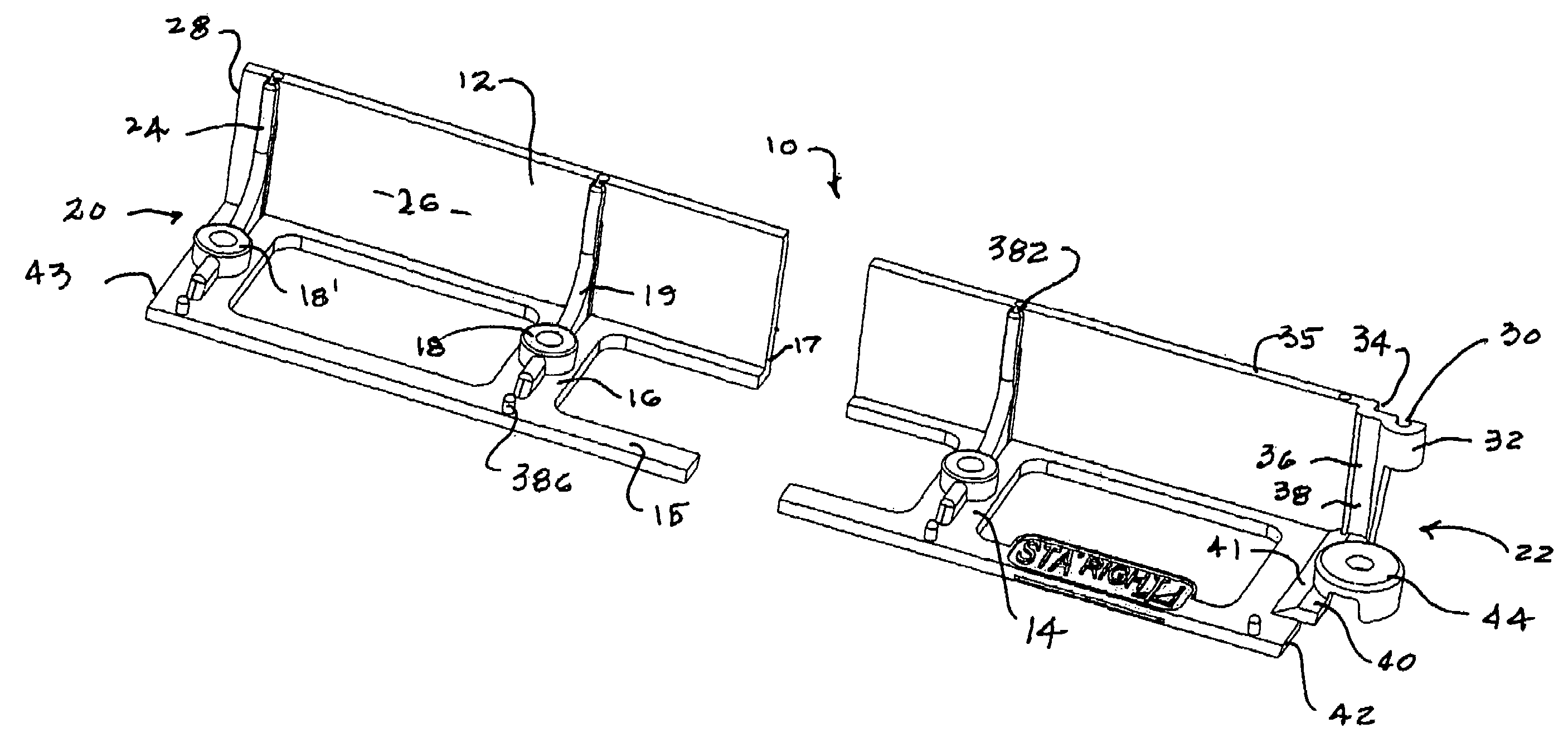
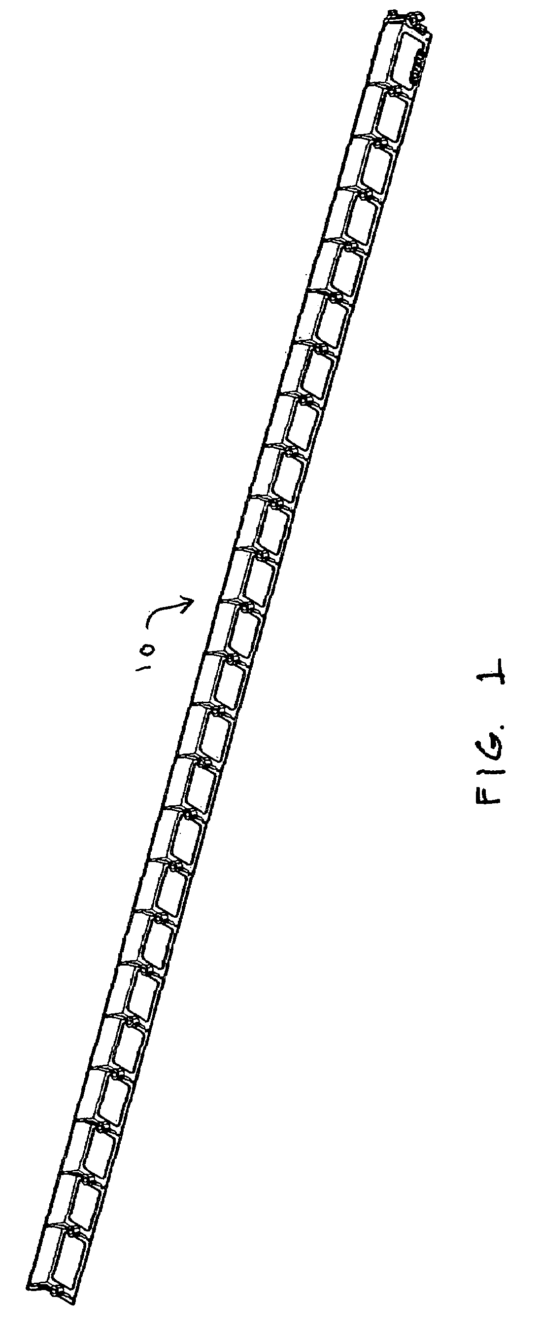
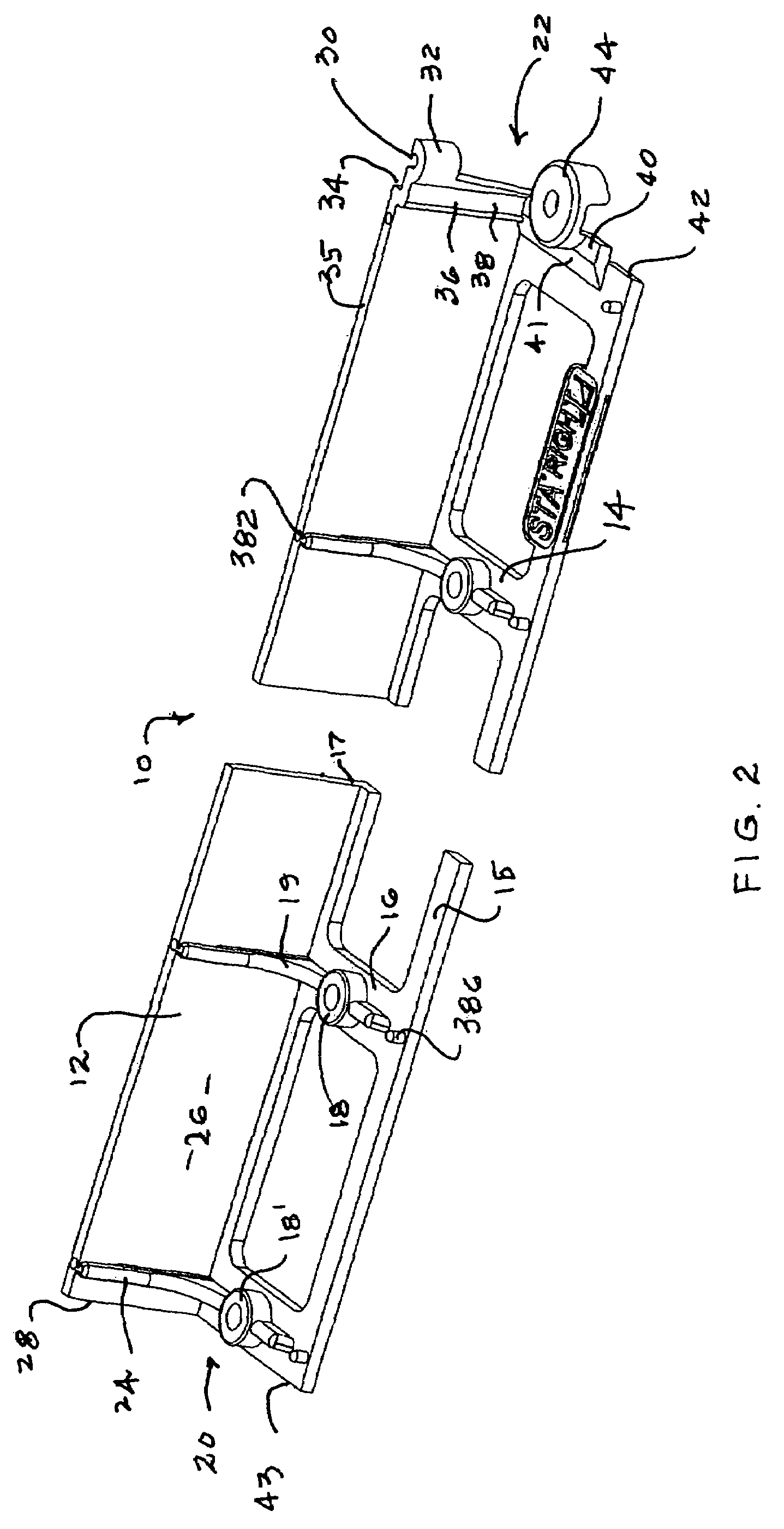
[0038]An elongated edger member 10 for holding landscaping materials and the like in place in a predetermined location which embodies the concepts and principles of the invention described herein is shown in FIGS. 1 and 2. Commercial embodiments of the member 10 may typically be about 4 feet long; however, the length of member 10 is not a critical feature of the invention. Generally speaking, although again not a critical feature of the invention, member 10 may be formed by injection molding of a thermoplastic material such as polyethylene. In accordance with the invention, member 10, as shown particularly in FIG. 2, ideally may be used for holding landscaping materials and the like in place in a predetermined location. Alternative, more structurally fortified embodiments of the invention described below may desirably be used for holding paving materials such as paving stones or bricks and the like in place in a predetermined location.

[0039]With particular reference to FIG. 2, it ca...


PUM


Abstract

An elongated edging assembly for holding landscaping and / or paving materials and the like in place in a predetermined location. The assembly may be made up of first and second elongated edger members which each include an elongated upright material retaining plate and a connector located adjacent an end of the corresponding member. The connectors desirably include respective mating interengageable components located on the plates near the ends thereof. The components are configured and adapted to cooperate to interconnect the members and maintain the ends of the respective plates in substantial abutting relationship with the plates in substantial alignment. The members may ideally be arranged as a neat packet of related objects including a pair of elongated members configured, arranged, aligned and joined together so as to present a single elongated construct having an open interior. At least one accessory item for said members is arranged within the open interior.

Description

CROSS REFERENCE TO RELATED APPLICATION[0001]NoneBACKGROUND OF THE INVENTION[0002]1. Field of the Invention[0003]This invention relates to elongated edging or holding devices having particular utility for holding landscaping and / or paving materials in place in defined areas. In particular the invention relates to such devices which are flexible and economical to install and which adapt readily to various shapes of areas. Even more particularly the invention relates to a novel connector structure whereby a plurality of the devices may be readily arranged in end-to-end relationship and held securely together in an edge defining array.[0004]2. The Prior Art Background[0005]Elongated landscape retaining or edging strips are elongated barriers installed longitudinally along the surface of the ground such that the barrier is substantially perpendicular to the ground. Such edging strips are used in diverse applications including such things as the retention and / or separation of beds of eart...

Claims


Application Information

Patent Timeline
Patent Type & Authority Patents(United States)
IPC IPC(8): E01C11/22A01G9/28
CPCA01G1/08E01C11/221A01G9/28
Inventor STROBL, JR., FREDERICK P.LEGARE, BRADLEY D.
Owner BRAVO FOXTROT HLDG
Why Eureka
Try Eureka