Bucket transfer apparatus

a transfer apparatus and bucket technology, applied in the direction of de-stacking, loading/unloading, gripping heads, etc., can solve the problems of troublesome storage of all the buckets on the cart, and difficult storage, and achieve automatic and smooth storage operation

Inactive Publication Date: 2010-08-17
YUYAMA MFG CO LTD
View PDF17 Cites 14 Cited by
  • Summary
  • Abstract
  • Description
  • Claims
  • Application Information

AI Technical Summary

Benefits of technology

[0009]A conventional storage rack, arranged to prevent falling off of buckets during transfer, was provided with projections on both ends of guiding grooves of the racks so that it was hard to store the buckets from directions parallel to the racks. According to the arrangement of the present invention, since buckets are stored from obliquely above, it is possible to smoothly deliver the buckets to the racks.
[0011]When pushing the bucket out by the push-out portions, a rear wall of the bucket, below a brim portion on its rear end side, is pushed, and when a front end of the bucket is located above a lower edge portion of the storage rack on an intrusion side, the opening / closing arms are opened while descending to move the bucket down while releasing the holding condition of the bucket. Thus, it is possible to smoothly store the bucket on a storage rack of the cart with the use of a simple arrangement.
[0013]The turning means is driven and controlled so as to allow the identification card to be read by the reading means, and the bucket is transferred to the cart by the transfer means so that the identification card is located on the same surface side. Thus, it is possible to reliably and easily read the identification card irrespective of the direction of the bucket.
[0016]According to the present invention, since buckets can be stored from obliquely above with respect to the storage rack, it is possible to achieve the effect of performing storage operations automatically and smoothly.

Problems solved by technology

However, since it is ineffective to individually transfer those buckets from the nurse station to the respective patient rooms, a plurality of buckets are stored in a cart whereupon they are collectively transferred.
However, it is extremely troublesome to store all of the many buckets on the cart.
Moreover, due to employment of an arrangement that prevents the stored buckets from falling off during transfer on the cart, there is a drawback in that they are hard to store.

Method used


Image

  • Bucket transfer apparatus
  • Bucket transfer apparatus
  • Bucket transfer apparatus

Examples


Embodiment Construction

[0025]An embodiment of the present invention will be explained in accordance with the accompanying drawings.

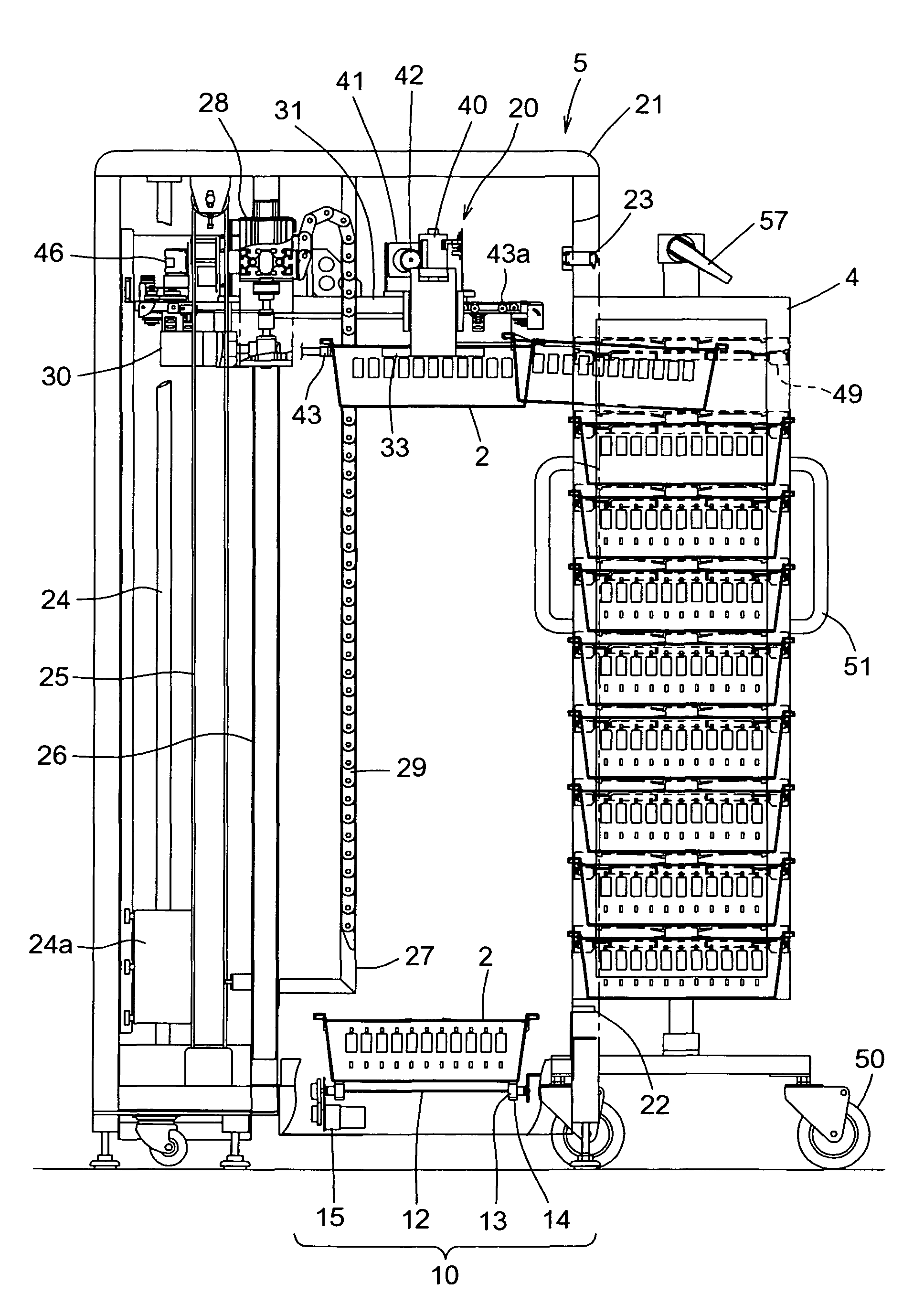
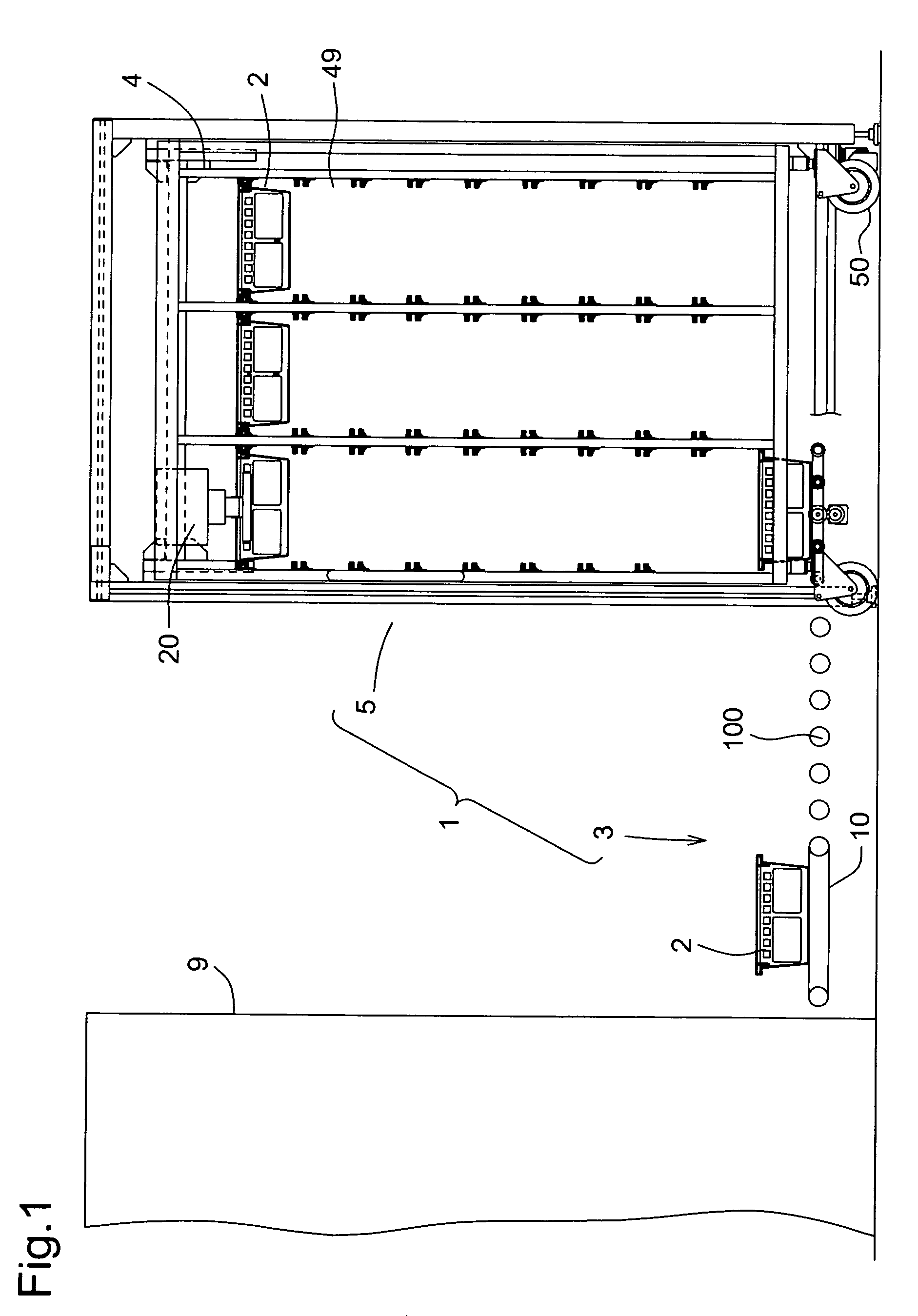
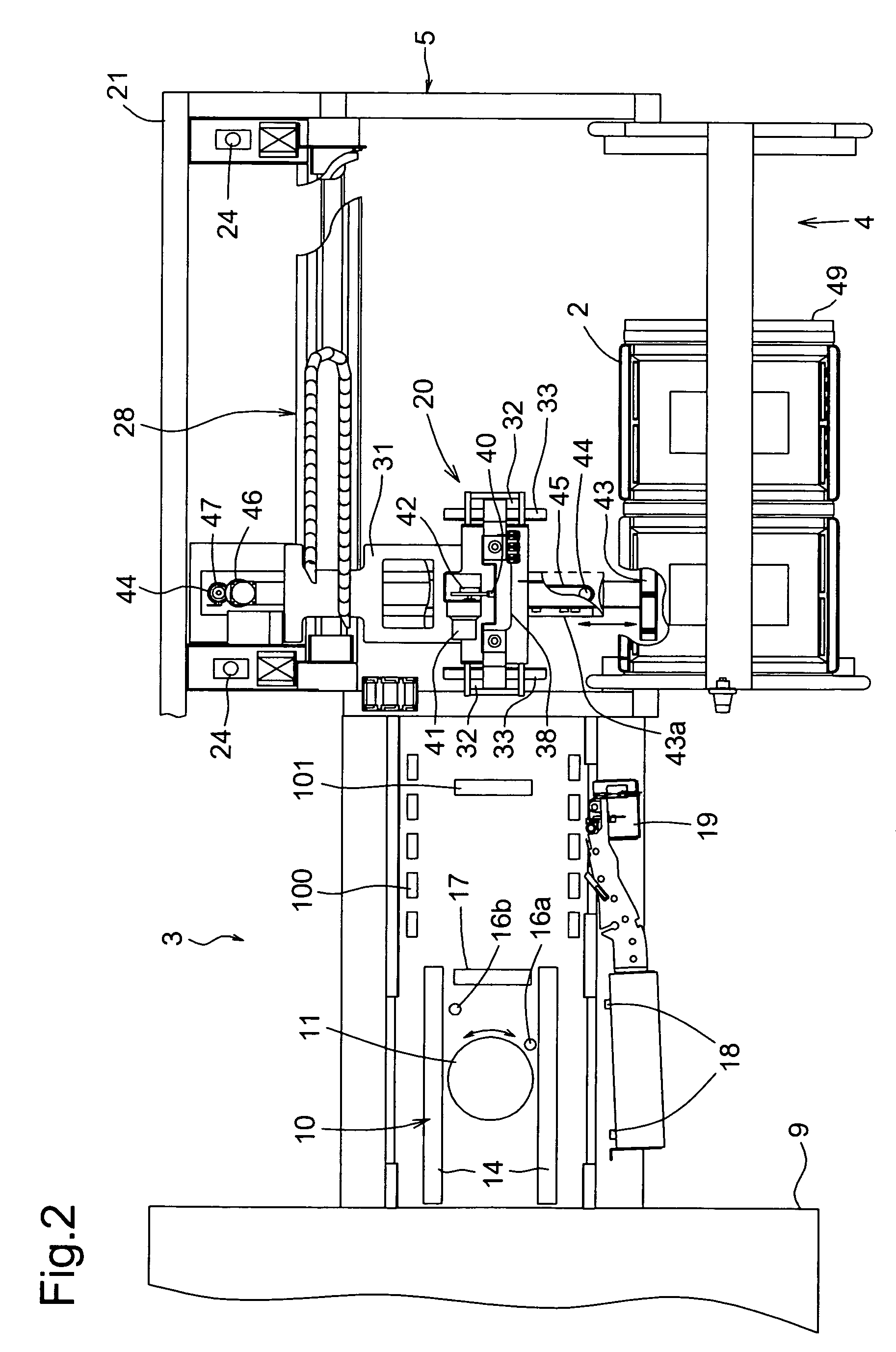
[0026]FIGS. 1 to 3 show a bucket transfer apparatus 1 according to the present embodiment. This transfer apparatus 1 includes a direction-changing portion 3 for changing directions of buckets 2, and a transfer portion 5 for transferring the buckets 2 to a cart 4.

[0027]As shown in FIG. 4A and FIG. 4B, the bucket 2 has a box-like shape with an open top, and a brim portion 6 is formed at an aperture edge thereof. Engaging concaves 7 are respectively formed on both side portions atop of the brim portion 6 by providing projections on two spots, respectively. An identification card 8 is attachable / detachable on an end surface of the bucket 2. The identification card 8 may be a leuco-type or thermochromic-type of rewritable card capable of being rewritten upon heating to a specified temperature. The identification card 8 bears pieces of patient information as shown in FIG. 7.

[0028]Th...


PUM


Abstract

A bucket carrier for carrying buckets (2) to store them in each storage shelf of a cart (4), the bucket carrier comprising a holding means (20) for holding buckets (2), and carrier means (28) for carrying the buckets (2) held by the holding means (20) to each storage shelf (49) of the cart (4). The arrangement is such that the holding means (20) and a transfer means (49) are drive-controlled so that the buckets (2) are stored in the storage shelves (49) obliquely from above. Thereby, the buckets (2) can be automatically stored in the cart (4).

Description

BACKGROUND OF THE INVENTION[0001]1. Technical Field[0002]The present invention relates to a bucket transfer apparatus.[0003]2. Description of the Related Art[0004]When transferring medications from a pharmacy department, medications for one patient are conventionally placed in a bucket and are automatically transferred to a nurse station using a transfer apparatus (see, for instance, Japanese Laid-Open Patent Publication No. 8-310625). However, since it is ineffective to individually transfer those buckets from the nurse station to the respective patient rooms, a plurality of buckets are stored in a cart whereupon they are collectively transferred.[0005]However, it is extremely troublesome to store all of the many buckets on the cart. Moreover, due to employment of an arrangement that prevents the stored buckets from falling off during transfer on the cart, there is a drawback in that they are hard to store. Thus, it has long been desired to provide an arrangement in which buckets c...

Claims


Application Information

Patent Timeline
Patent Type & Authority Patents(United States)
IPC IPC(8): B65G1/00B65G1/04B65G1/137B65G65/00
CPCB65G65/00B25J15/0491B65G1/0457B65G1/137B65G61/00
Inventor KOIKE, NAOKIKOSHIO, HIROYUKIKUNIMOTO, TATSUAKIITOU, TAKASHI
Owner YUYAMA MFG CO LTD
Why Eureka
Try Eureka