Interposer assembly with flat contacts

a technology of interposer assembly and contact, which is applied in the direction of coupling contact member, coupling device connection, printed circuit, etc., can solve the problems of unpredictability of friction and wear characteristics, and achieve the effect of improving the durability of surface plating

Inactive Publication Date: 2010-08-17
AMPHENOL CORP
View PDF35 Cites 10 Cited by
  • Summary
  • Abstract
  • Description
  • Claims
  • Application Information

AI Technical Summary

Benefits of technology

[0009]When the interposer assembly is sandwiched between circuit members, the contact tips engage closely spaced pads on circuit members, and are forced perpendicularly into the into passages in the plate with very limited lateral shifting. As a result, the contact tips reliably engage very small, closely spaced contact pads.
[0010]The flat shaped conductor is highly compliant to ensure contact pressure is maintained between contact tips and pads on the circuit members even if the pads are not moved into flush engagement with the top or bottom surfaces of the interposer assembly plate. High compliance is obtained by providing beams spaced along the length of the conductor and extending back and forth across the slot in a serpentine shape and by elastically bending the beams within the thickness of the contact when the interposer assembly is sandwiched between opposed circuit members. The conductor is stressed with minimum engagement with the interposer assembly plate.
[0012]The interposer assembly contacts may be manufactured by etching or stamping strip metal stock. The tips of the flat contact may be rounded to eliminate sharp points which may otherwise produce undesirable friction and wear characteristics resulting from the manufacturing process, such as etching or stamping, where a sharp or burred edge may exist. The formed contacts are plated. The rounded contact profile produces a more consistent wear profile and improves the durability of the surface plating on the contact and on the mating pad.

Problems solved by technology

The edges of etched contacts may have sharp points which may produce unpredictable friction and wear characteristics when mated with pads.

Method used


Image

  • Interposer assembly with flat contacts
  • Interposer assembly with flat contacts
  • Interposer assembly with flat contacts

Examples


Embodiment Construction

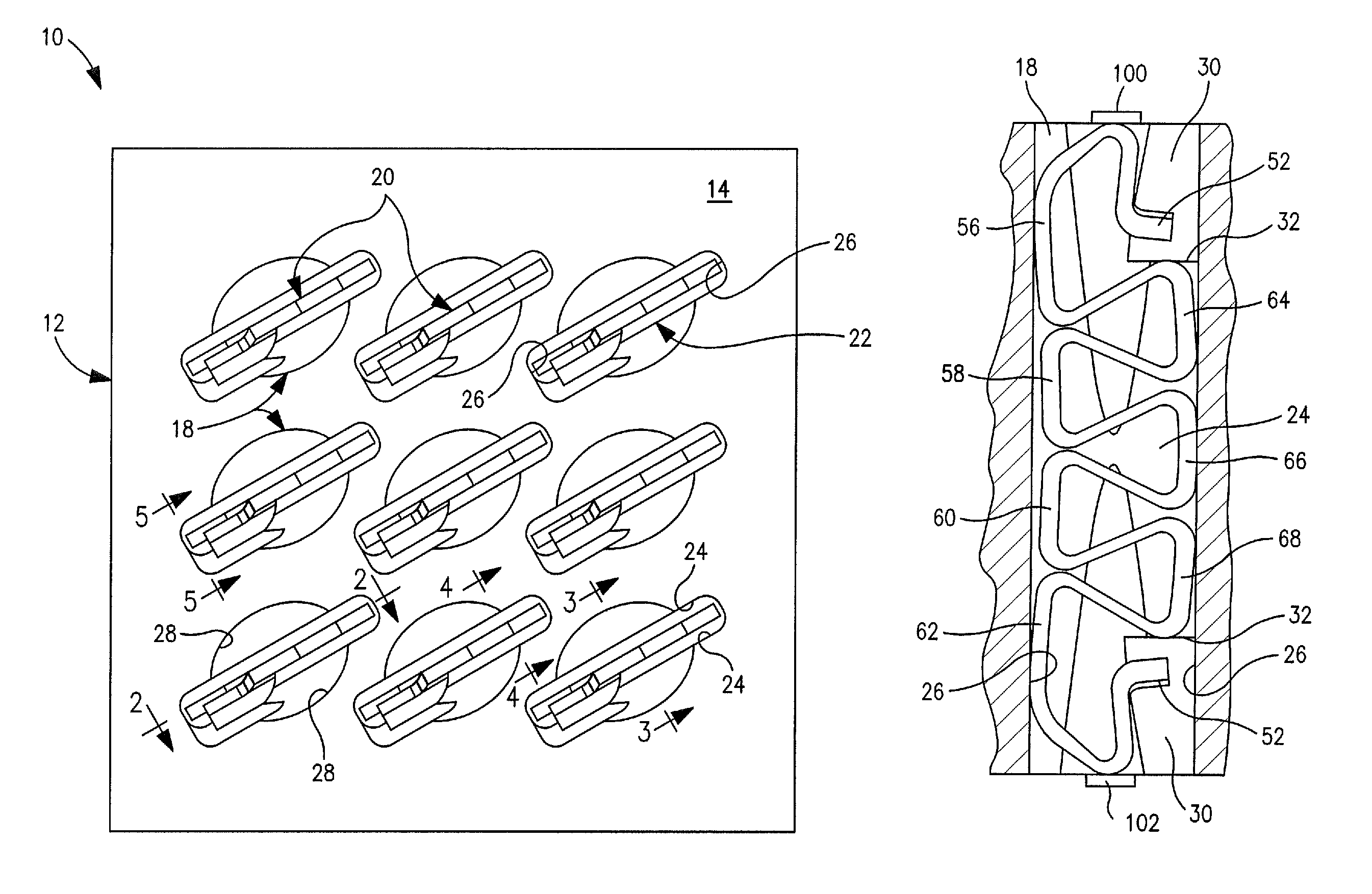
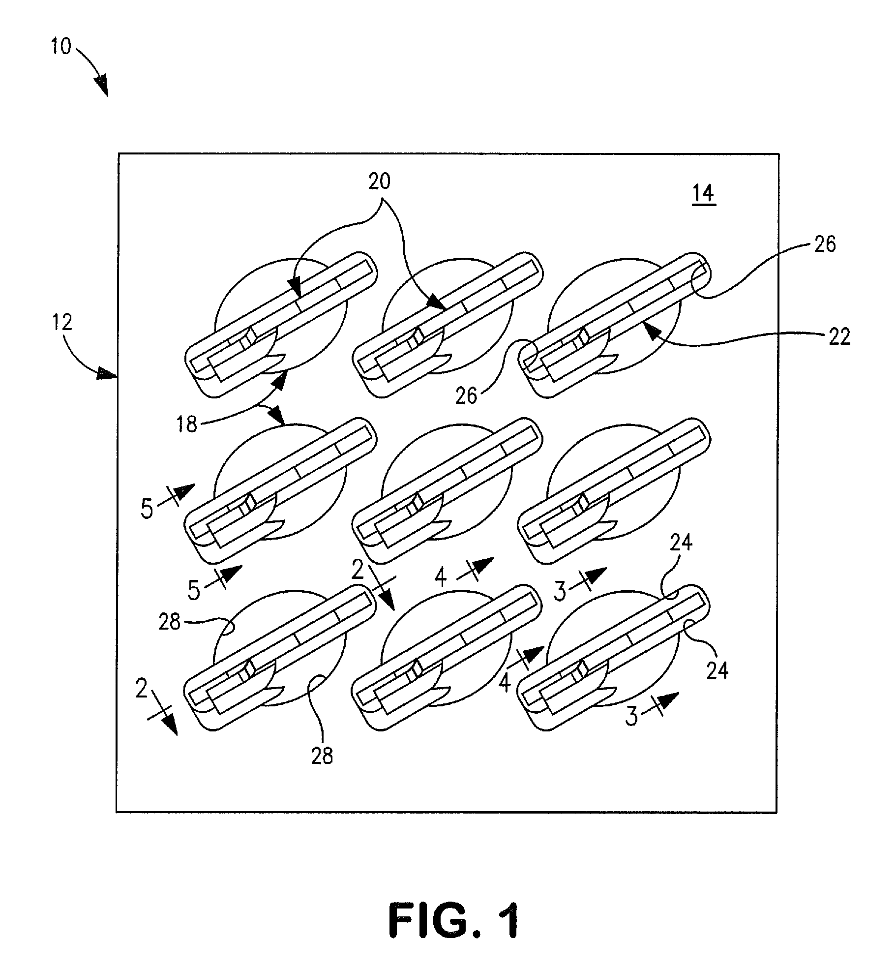
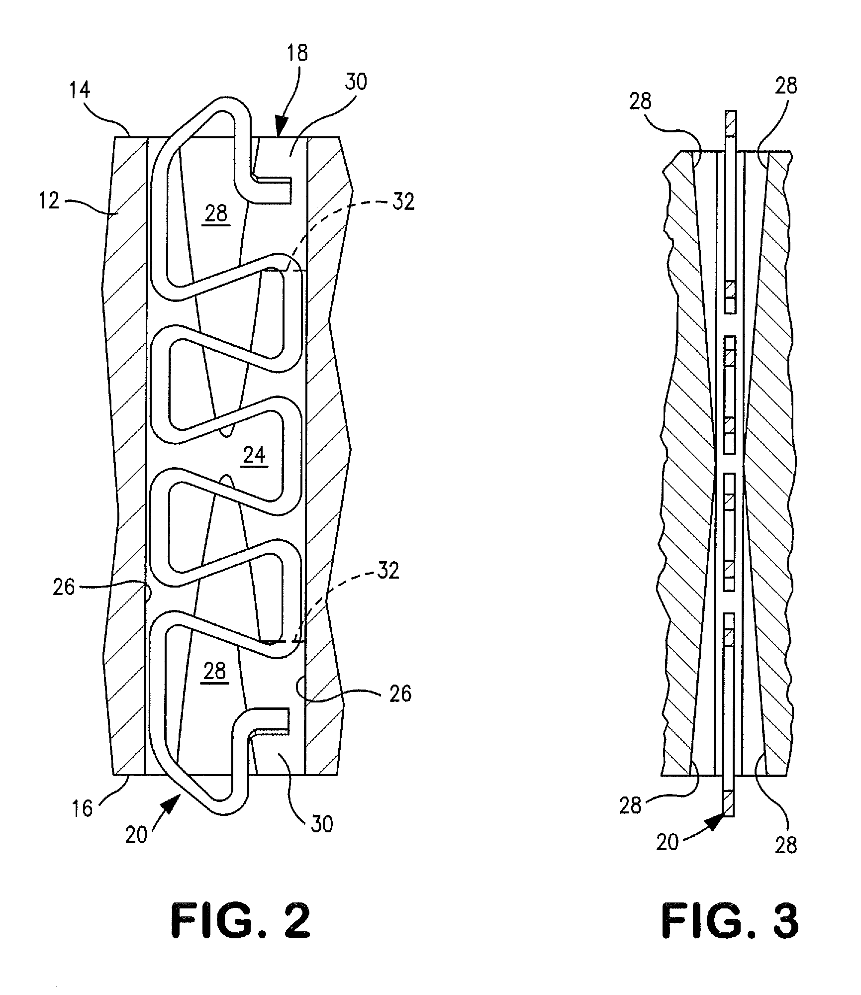
[0023]Interposer assembly 10 includes a thin substrate or plate 12 molded from thermoplastic resin or other suitable dielectric material and having opposed, parallel top and bottom surfaces 14 and 16, a plurality of through passages 18 extending between the top and bottom surfaces, and flat contacts 20 positioned in passages 18. The plate 12 may be molded from a liquid crystal polymer or from other suitable thermoplastic material.

[0024]Each passage 18 includes a narrow slot 22 extending between the top surface 14 and bottom surface 16 of plate 12. The slot has flat, opposed and closely spaced sidewalls 24 and narrow, parallel end walls 26, as shown in FIGS. 1-5. End walls 26 are straight and extend perpendicular to plate surfaces 14 and 16. The walls 26 are slightly concave along their lengths in order to center contacts 20 in the slots between the sidewalls.

[0025]Two partial conical recesses 28 extend inwardly along each sidewall 24 from the top and bottom surfaces of the plate nea...


PUM


Abstract

Interposer assembly includes an insulating plate with slots extending through the thickness of the plate and a flat metal contacts confined in the slots.

Description

FIELD OF INVENTION[0001]The invention relates to interposer assemblies used for forming electrical connections between spaced contact pads on circuit members.DESCRIPTION OF THE PRIOR ART[0002]Interposer assemblies are used for forming electrical connections between densely spaced contact pads on adjacent, parallel circuit members. The pads on the members are arranged in identical patterns. Commonly, the circuit members are circuit boards or ceramic plates carrying integrated circuits.[0003]The interposer assembly includes an insulating plate and a plurality of through-contacts carried in passages in the plate and arranged in the same pattern as the pads on the circuit members. The contacts have contact tips projecting above the top and bottom surfaces of the plate. The interposer assembly is sandwiched between the two circuit members which are held together with the contacts forming electrical connections between aligned pairs of pads. Conventional interposer assemblies are disclose...

Claims


Application Information

Patent Timeline
Patent Type & Authority Patents(United States)
IPC IPC(8): H01R12/00
CPCH01R13/2428
Inventor NEIDICH, DOUGLAS A.TAYLOR, PAUL R.
Owner AMPHENOL CORP
Why Eureka
Try Eureka