Substrate treatment method and substrate treatment apparatus

a substrate treatment and substrate technology, applied in the direction of liquid surface applicators, electrical devices, coatings, etc., can solve the problems of air bubbles liable to reside in the space filled with treatment liquid, air originally present in the space is likely to be trapped in the space, and the treatment does not proceed as desired on the substrate area, so as to prevent contamination of the substrate and reliably remove the space

Inactive Publication Date: 2009-04-30
DAINIPPON SCREEN MTG CO LTD
View PDF8 Cites 4 Cited by
  • Summary
  • Abstract
  • Description
  • Claims
  • Application Information

AI Technical Summary

Benefits of technology

[0014]The treatment liquid replacing step may include the step of supplying the treatment liquid into the space between the one surface of the substrate and the plate from the spout through a pipe through which the pre-supply liquid is supplied to the spout. In this case, the pre-supply liquid and the treatment liquid are supplied through the common pipe and spouted into the space, so that the pre-supply liquid is substantially prevented from remaining in the pipe. This prevents contamination of the substrate which may otherwise occur when the pre-supply liquid drips from the pipe.
[0015]Further, the treatment liquid supplied into the space does not hinder liquid flow in th

Problems solved by technology

Therefore, when the space between the surface of the substrate and the plate is filled with the treatment liquid, air originally present in the space is likely to be trapped in the space.
As a result, air bubbles are liable to reside in the space filled with the treatment liquid.
The air bubbles

Method used


Image

  • Substrate treatment method and substrate treatment apparatus
  • Substrate treatment method and substrate treatment apparatus
  • Substrate treatment method and substrate treatment apparatus

Examples


Embodiment Construction

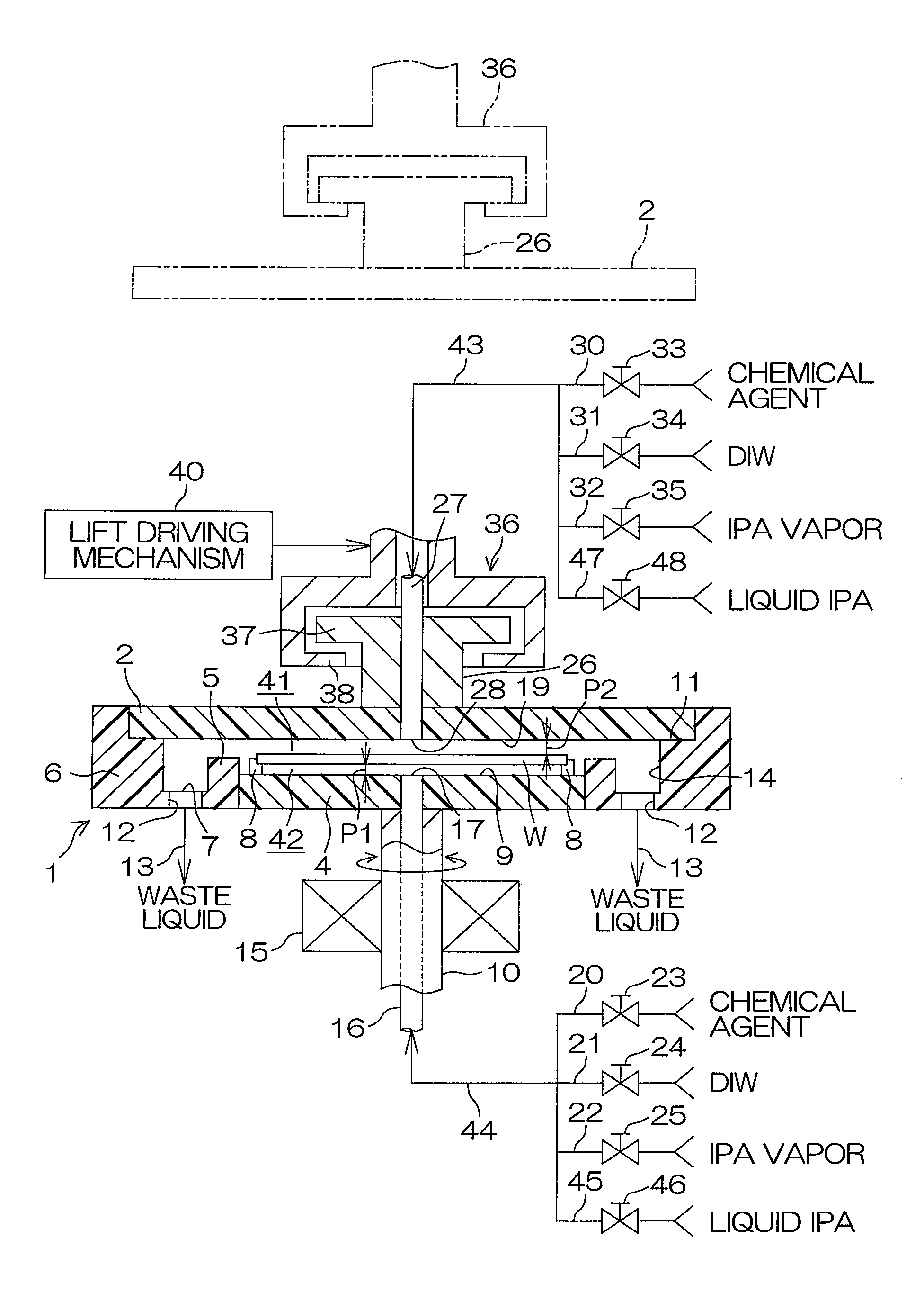
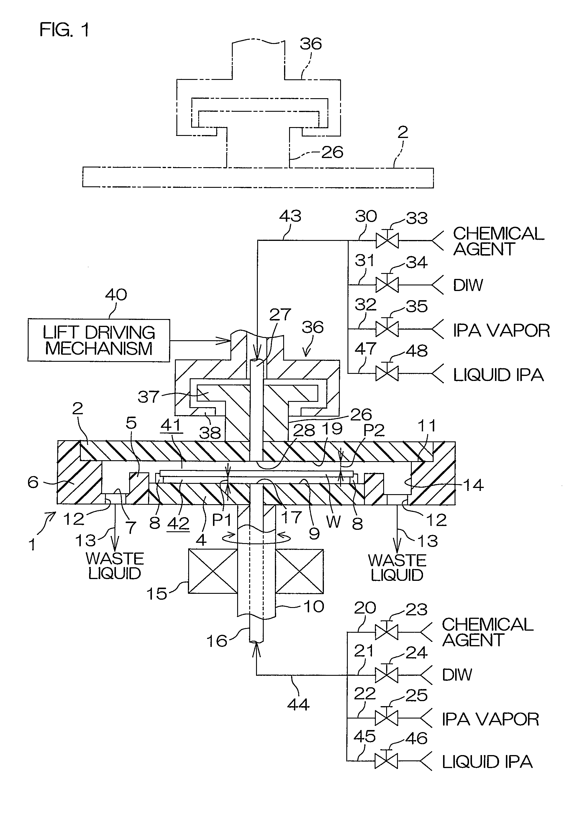
[0024]FIG. 1 is a sectional view schematically showing the construction of a substrate treatment apparatus according to one embodiment of the present invention.

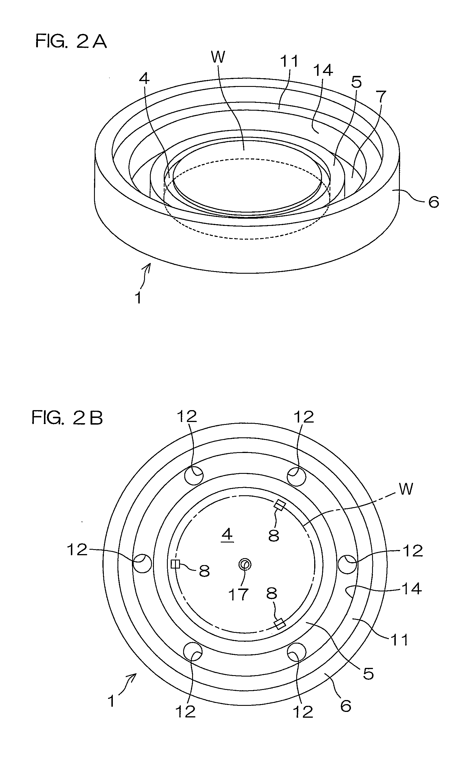
[0025]The substrate treatment apparatus is of a single substrate treatment type which treats front and back surfaces of a semiconductor wafer W as an exemplary substrate (hereinafter referred to simply as “wafer”) with a treatment liquid. The substrate treatment apparatus includes a lower substrate holding member 1 of a generally cylindrical bottomed shape for holding the wafer W, and an upper plate 2 of a disk shape opposed to the lower substrate holding member 1 above the lower substrate holding member 1. A chemical agent and DIW (deionized water) are used as the treatment liquid for the treatment of the front and back surfaces of the wafer W. Examples of the chemical agent include hydrofluoric acid, buffered hydrofluoric acid (buffered HF, which is a liquid mixture of hydrofluoric acid and ammonium fluoride), SC1 (ammonia-...


PUM


Abstract

An inventive substrate treatment method is performed by a substrate treatment apparatus including a plate having an opposed surface to be kept in opposed spaced relation to one surface of a substrate for treating the substrate with a treatment liquid, and includes: a pre-supply liquid filling step of supplying a pre-supply liquid into a space defined between the one surface of the substrate and the plate through a spout which is provided in the opposed surface in opposed relation to the center of the substrate, and filling the space with the pre-supply liquid, the pre-supply liquid having a smaller contact angle with respect to the substrate and the plate than the treatment liquid; a treatment liquid replacing step of, after a liquid-filled state is established in the space filled with the pre-supply liquid, supplying the treatment liquid into the space to replace the pre-supply liquid present in the space with the treatment liquid while keeping the space in the liquid-filled state; and a treatment liquid contacting step of, after the replacement of the pre-supply liquid, filling the space with the treatment liquid to cause the treatment liquid to contact the one surface of the substrate.

Description

BACKGROUND OF THE INVENTION[0001]1. Field of the Invention[0002]The present invention relates to a substrate treatment method and a substrate treatment apparatus. Exemplary substrates to be treated include semiconductor wafers, glass substrates for liquid crystal display devices, glass substrates for plasma display devices, glass substrates for FED (Field Emission Display) devices, substrates for optical disks, substrates for magnetic disks, substrates for magneto-optical disks, substrates for photo masks, and ceramic substrates.[0003]2. Description of Related Art[0004]In production processes for semiconductor devices and liquid crystal display devices, a substrate treatment apparatus of a single substrate treatment type is often used for treating a surface of a substrate such as a semiconductor wafer or a glass substrate for a liquid crystal display panel with a treatment liquid. The substrate treatment apparatus includes, for example, a substrate holding member which generally hor...

Claims


Application Information

Patent Timeline
IPC IPC(8): C23G1/02H01L21/30
CPCH01L21/6708H01L21/67051H01L21/306H01L21/683
Inventor UCHIDA, HIROAKIMAEGAWA, TADASHIANO, SEIJI
Owner DAINIPPON SCREEN MTG CO LTD
Why Eureka
Try Eureka