Apparatus and method for feeding fibers

a fiber mat and apparatus technology, applied in the field of apparatus and method for feeding fibers, can solve problems such as thin spots, and achieve the effect of smoothing out fluctuations and minimizing fluctuations in the weight of the discharged fiber ma

Inactive Publication Date: 2010-08-24
DILO MASCHF OSKAR
View PDF10 Cites 2 Cited by
  • Summary
  • Abstract
  • Description
  • Claims
  • Application Information

AI Technical Summary

Benefits of technology

[0005]It is an object of the present invention to provide a feeding device and a method for supplying opened fibers or fiber flocks, in which the variations in the weight of the discharged fiber mat are minimized and fluctuations are smoothed out.

Problems solved by technology

A basic problem of these types of devices is ensuring that the fibers which have been separated from the transport air stream in an upper section of the chute are distributed with uniform density across the width of the chute and also in the longitudinal direction.
Controlling the speed of the individual roll segments involves the problem that, when one of the roll segments of a roll is rotating at high speed, a thin spot can form, because not enough fresh material can be brought up from the rear to compensate.

Method used


Image

  • Apparatus and method for feeding fibers
  • Apparatus and method for feeding fibers
  • Apparatus and method for feeding fibers

Examples


Embodiment Construction

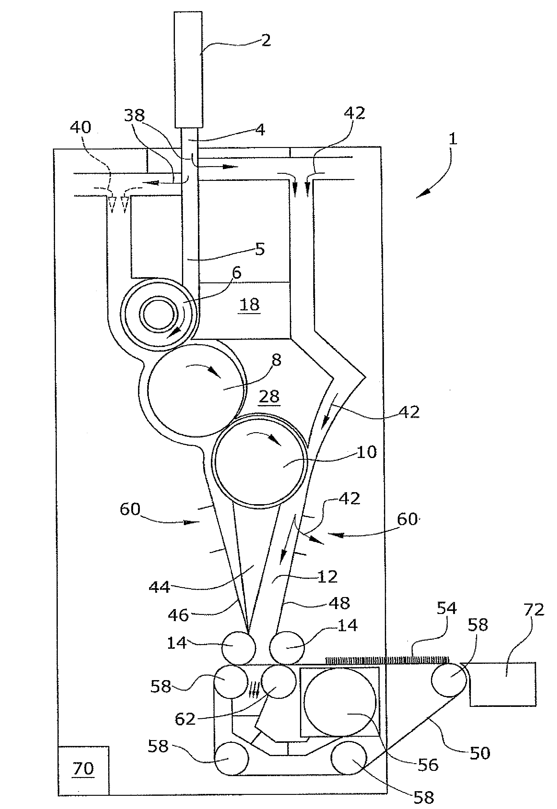
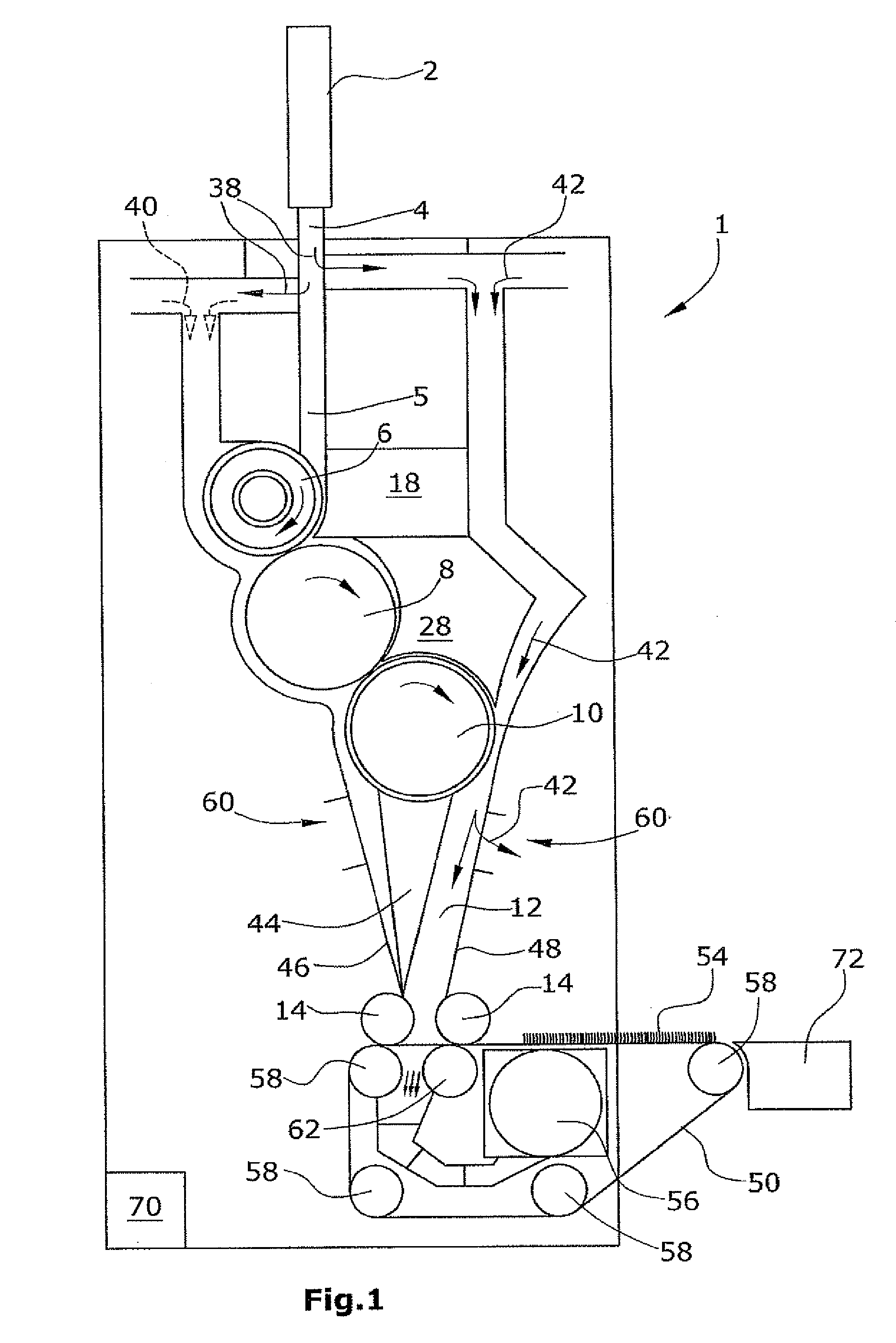
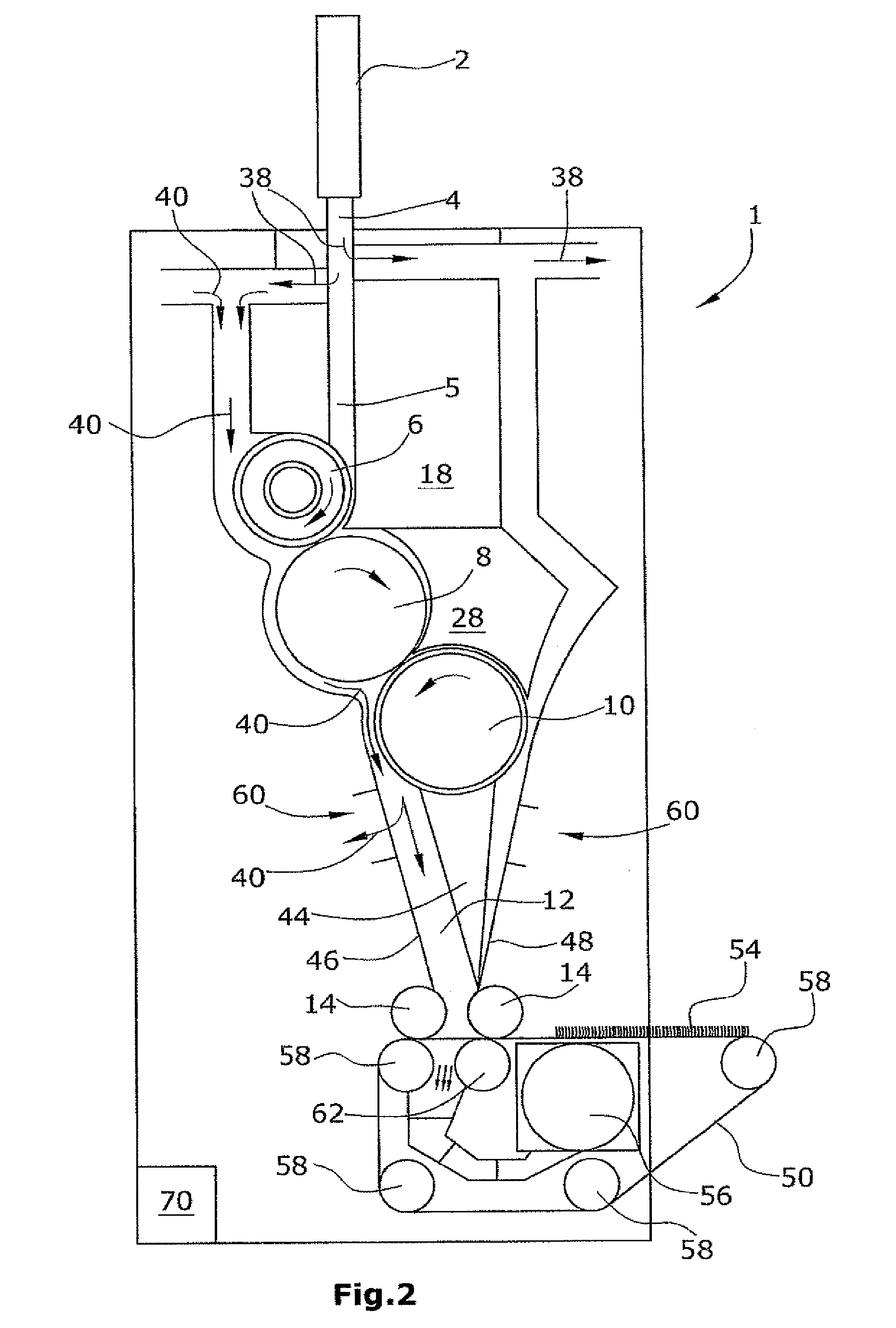
[0050]FIG. 1 shows a feeding device 1 for fiber flocks or opened fibers for feeding a downstream textile machine, especially either a carding machine or a downstream mechanical or thermal solidification device. As can be seen in FIGS. 1 and 6, the fiber flocks are supplied to a first upper vertical fiber chute 4 by means of a pneumatic fiber transport device 2, whereupon the transport air 38 is branched off from the air stream carrying the fibers by means of, for example, comb-like chute wall elements, so that the fiber flocks can collect in the upper fiber chute 4 and increase in density as they proceed toward the bottom end of the upper fiber chute 4. At the bottom end 5 of the upper fiber chute, the fiber flocks are sent to several rolls 6, 8, 10 to open the fiber flocks, which are then collected in a lower fiber chute 12. Discharge rolls 14 discharge a fiber mat at the bottom end of the fiber chute 12. In exemplary embodiments 1 to 3, the fiber mat is deposited onto a screen bel...


PUM

PropertyMeasurementUnit
circumferential velocityaaaaaaaaaa

Abstract

A feeding device for fiber flocks or opened fibers for feeding a textile machine, especially a carding machine, has a first, upper vertical fiber chute which supplies the fibers or fiber flocks to rolls for opening of the fibers, and a lower fiber chute which accepts the fibers released by the rolls and discharges a fiber mat at the bottom end of the fiber chute by way of discharge rolls. The feeding device also has a segmented intake trough with several intake trough segments which cooperate with a segmented, clothing-covered first roll, which is divided into several roll segments, wherein the torque of the roll segments can be controlled individually and the widths of the gaps between the intake trough segments and the associated roll segments can be adjusted on a segment-by-segment basis.

Description

CROSS REFERENCE TO RELATED APPLICATION[0001]This application claims priority based on European patent application EP 07 110 930.0, filed Jun. 25, 2007.FIELD OF THE INVENTION[0002]The invention pertains to feeding devices for fiber flocks or opened fibers for feeding textile machines, especially carding machines, and also pertains to methods for feeding fibers to textile machines.DESCRIPTION OF THE PRIOR ART[0003]In these types of feeding devices, the fiber mat supplied to the downstream textile machine should have a high degree of uniformity in both the longitudinal and transverse directions. A basic problem of these types of devices is ensuring that the fibers which have been separated from the transport air stream in an upper section of the chute are distributed with uniform density across the width of the chute and also in the longitudinal direction.[0004]It is known from EP 0 972 866 A that an equalizing device consisting of segmented rolls can be provided downstream of the feed...

Claims


Application Information

Patent Timeline
Patent Type & Authority Patents(United States)
IPC IPC(8): D01G15/40
CPCD01G23/06
Inventor BERNHARDT, SIEGFRIEDKAMPRATH, ROBERTNAUMANN-BURGHARDT, HEINZ-WERNER
Owner DILO MASCHF OSKAR
Why Eureka
Try Eureka