Wire bonding method for forming low-loop profiles

a wire loop and profile technology, applied in the direction of auxillary welding devices, soldering devices, semiconductor/solid-state device details, etc., can solve the problems of weak strength of the neck portion of the wire bond, weakened adhesion between the ball bond and the bonding surface, and more susceptible to neck cracks and breakag

Active Publication Date: 2010-08-24
ASM TECH SINGAPORE PTE LTD
View PDF9 Cites 104 Cited by
  • Summary
  • Abstract
  • Description
  • Claims
  • Application Information

AI Technical Summary

Benefits of technology

[0008]It is thus an object of the invention to seek to provide a method of forming a wire bond wherein a height of a wire loop connecting different bonding points may be reduced while avoiding some of the aforesaid disadvantages of prior art wire bonds.

Problems solved by technology

A problem with this approach of crushing the bonding wire by bonding it to the ball bond is that the strength of the neck portion of the wire bond is weak.
This makes it more susceptible to neck crack and breakage.
Further, the crushing of the bonding wire onto the ball bond may weaken the strength of the ball bond, resulting in weakened adhesion between the ball bond and the bonding surface.
Thus, there is unnecessary wastage of bonding wire.

Method used


Image

  • Wire bonding method for forming low-loop profiles
  • Wire bonding method for forming low-loop profiles
  • Wire bonding method for forming low-loop profiles

Examples


Embodiment Construction

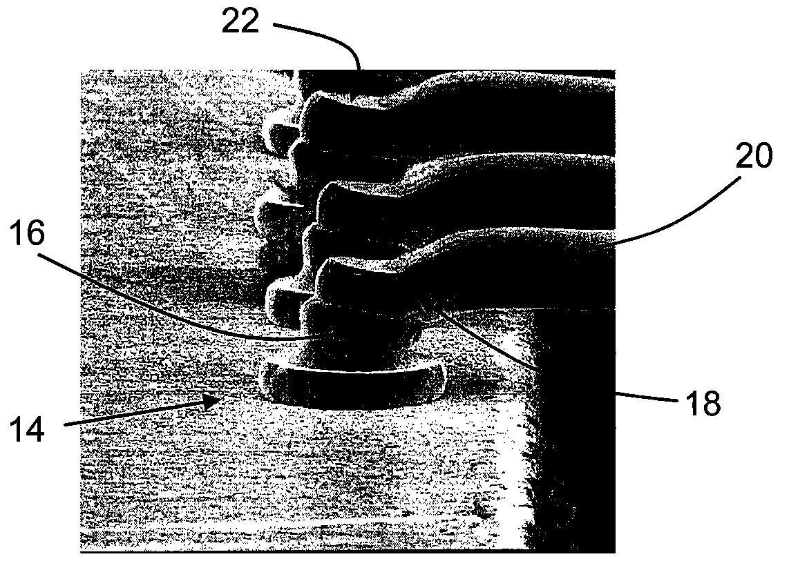
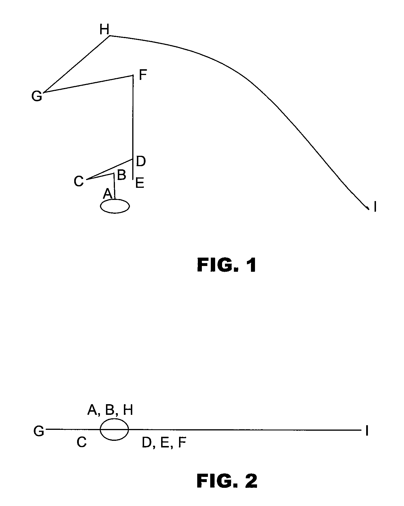
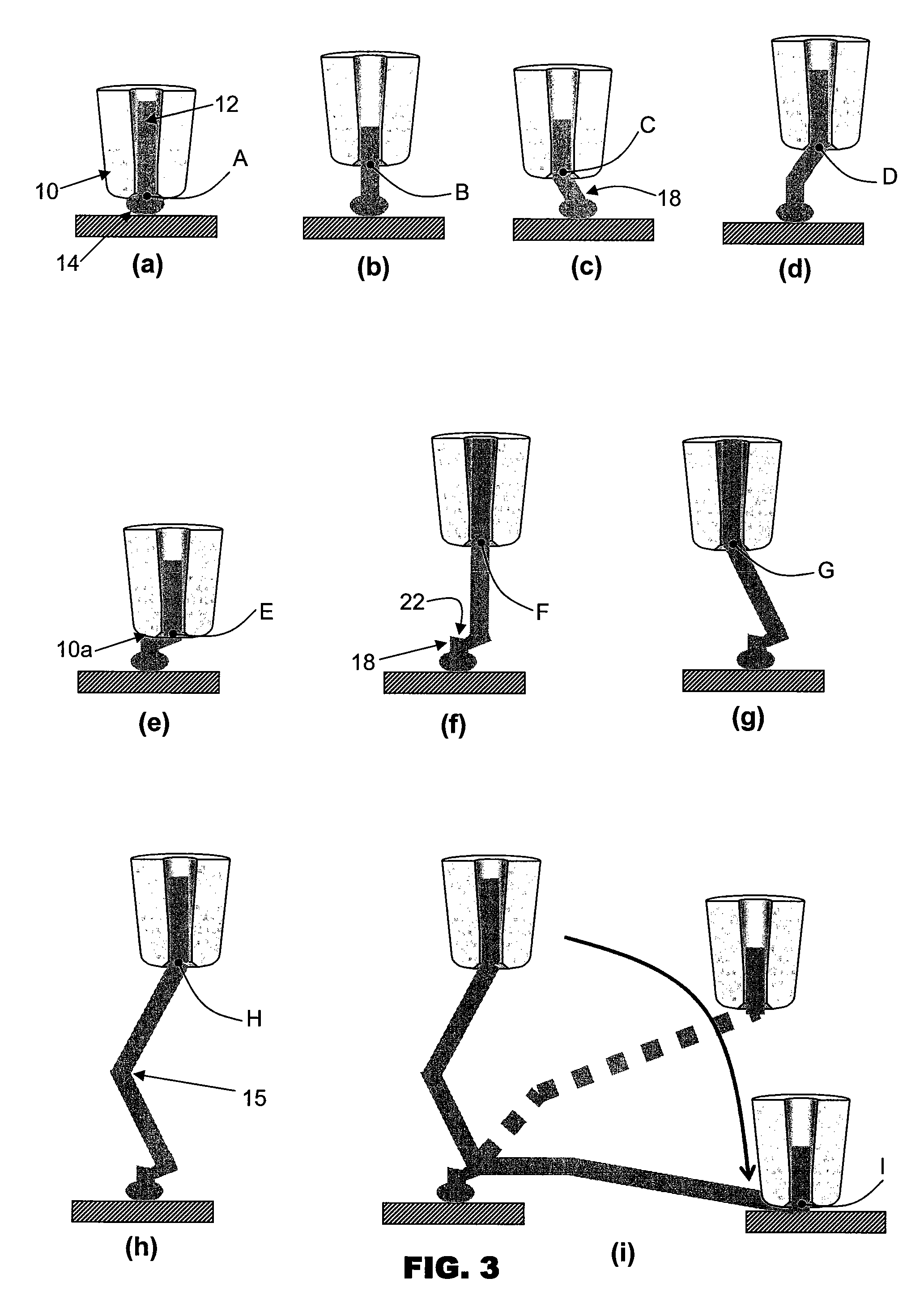
[0017]FIG. 1 is side view of a loop motion profile of a wire bonding tool 10 employing a wire bonding method according to the preferred embodiment of the invention. FIGS. 3(a) to 3(i) are diagrammatic illustrations showing the shapes of a bonding wire 12 at different positions of a bonding tool 10 during loop formation

[0018]The bonding tool, such as a capillary 10, is used to feed bonding wire 12 to bond the wire between a first bonding position A and a second bonding position I. A ball bond 14 is first made at the first bonding position A. The capillary 10 is then moved substantially vertically upwards away from the first bond 14 to point B.

[0019]At point B, the capillary 10 is moved in a reverse motion diagonally downwards and in a direction away from a second bonding position I to point C. This reverse motion forms a neck portion 18 at the top of the ball bond 14 and bends the wire 12. From point C, the capillary 10 is moved diagonally upwards to point D towards the direction of ...


PUM

PropertyMeasurementUnit
circumferenceaaaaaaaaaa
heightaaaaaaaaaa
ultrasonic energyaaaaaaaaaa

Abstract

A method of forming a wire bond with a bonding tool is provided that comprises the steps of forming a ball bond onto a bonding surface, raising the bonding tool away from the ball bond to form a neck portion integrated with a top of the ball bond, locating a circumference of a tip of the bonding tool onto the neck portion, pressing the neck portion with the circumference of the tip to form a depression in the neck portion without bonding the neck portion to the ball bond, and thereafter raising the bonding tool away from the ball bond.

Description

CROSS REFERENCE TO RELATED APPLICATION[0001]This application claims the benefit and priority of U.S. Provisional Application Ser. No. 60 / 810,782 filed Jun. 2, 2006, and entitled WIRE BONDING METHOD FOR FORMING LOW-LOOP PROFILES, the disclosure of which is incorporated herein by reference.FIELD OF THE INVENTION[0002]The invention relates to wire bonding to electrically connect different electrical contact pads of electronic components using wires, and in particular, to the formation of wire loops with low height profiles.BACKGROUND AND PRIOR ART[0003]During certain semiconductor assembly processes, semiconductor dice are placed on a carrier such as a leadframe substrate. Electrical connections in the form of wire bonds are then made between the dice and substrate, or between individual dice. Gold, aluminium or copper wires are commonly used to make these connections. Wire bonds are formed at bonding sites where the electrical connections are to be made, typically using an ultrasonic ...

Claims


Application Information

Patent Timeline
Patent Type & Authority Patents(United States)
IPC IPC(8): B23K31/02
CPCB23K20/004B23K20/007H01L24/48H01L24/85H01L24/45H01L24/78H01L2224/45124H01L2224/45144H01L2224/45147H01L2224/48247H01L2224/48465H01L2224/48599H01L2224/48699H01L2224/78301H01L2224/85181H01L2924/01005H01L2924/01013H01L2924/01014H01L2924/01029H01L2924/01079H01L2924/14H01L2924/00014H01L2924/01006H01L2924/01033H01L2924/00H01L2224/48095H01L2224/85205H01L2224/85399H01L2224/05599
Inventor WONG, YAM MOGOH, MOW HUAT
Owner ASM TECH SINGAPORE PTE LTD
Why Eureka
Try Eureka