Detection signal generator circuit for an RFID reader

a detection signal and generator circuit technology, applied in the field of rfid systems, can solve the problems of reducing affecting the service life of the reader,

Active Publication Date: 2010-08-24
ASSA ABLOY AB
View PDF28 Cites 10 Cited by
  • Summary
  • Abstract
  • Description
  • Claims
  • Application Information

AI Technical Summary

Problems solved by technology

Although a reader can continuously operate in the data transaction state, the functions performed by the reader while in the data transaction state typically have a relatively high power demand, which can rapidly deplete the power supply of the reader.
This condition is particularly undesirable when the reader is powered by a self-contained portable power supply, such as a small disposable or rechargeable battery, which has a finite life.
In particular, inductive coupling of the reader antenna to the nearby transponder antenna causes a change in the impulse response on the reader antenna.
However, the entire population of transponders in a given RFID system is not always tuned to the same single resonant frequency.

Method used


Image

  • Detection signal generator circuit for an RFID reader
  • Detection signal generator circuit for an RFID reader
  • Detection signal generator circuit for an RFID reader

Examples


Embodiment Construction

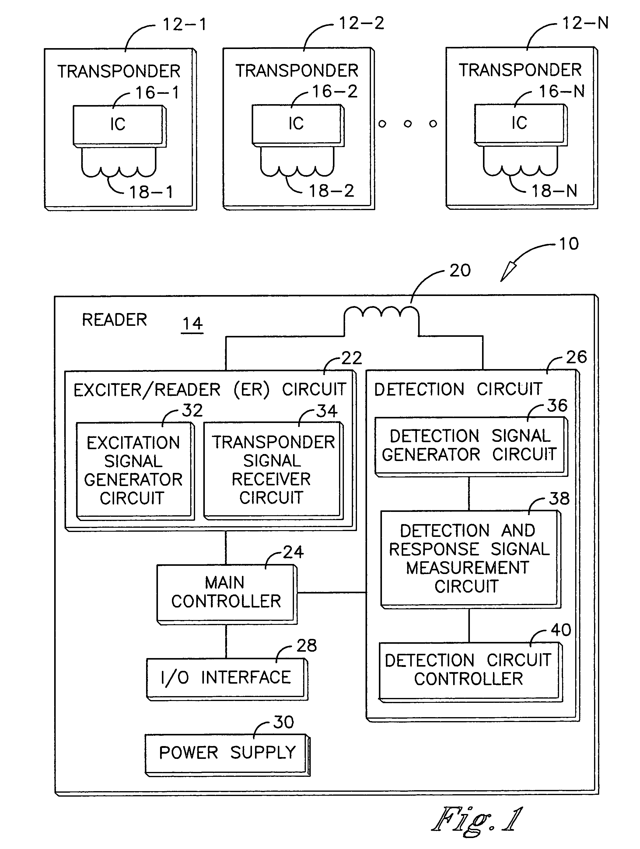
[0036]An RFID system is shown in FIG. 1 and generally designated 10. The RFID system 10 comprises a plurality of transponders 12-1 through 12-N and a reader 14. The transponders 12-1 through 12-N are preferably passive transponders which do not require an internal power supply. Instead the electrical power required to operate the passive transponders is supplied to the transponders by electromagnetic energy transmitted from a reader. Accordingly, the passive transponders are operational when they receive electromagnetic oscillations from a reader, which are of a specific frequency and of a sufficient strength to power up the transponder.

[0037]Each transponder 12 comprises a number of functional elements including a transponder integrated circuit (IC) 16 and a transponder antenna 18. The transponder IC 16 embodies the processing and memory capabilities of the transponder 12. The transponder antenna 18 is coupled to the transponder IC 16 and is a conventional coil termed a “dual-funct...


PUM


Abstract

An RFID transponder detector is provided having a coupled oscillator system. Coupled first and second LC of the system produce a detection signal each time a combination of pulses is applied to the LC pairs. Application of the pulses is repeated periodically to produce a sequence for detection signals having two different first and second detection frequencies. Transmitting the sequence of detection signals results in corresponding first and second response signals having the first and second detection frequencies at the LC pairs. Values of a preselected detection parameter for the detection signals are compared to the values of the detection parameter for the response signals to determine if a transponder having a transponder resonant frequency corresponding to the first or second detection frequency is present in a proximal space of the transponder detector.

Description

TECHNICAL FIELD[0001]The present invention relates generally to RFID systems and, more particularly, to the construction and operation of a detection signal generator circuit utilized within a reader of an RFID system.BACKGROUND OF THE INVENTION[0002]Radio frequency identification (RFID) systems typically include at least one reader and a plurality of transponders, which are commonly termed credentials, cards, tags, or the like. The transponder may be an active or passive radio frequency communication device which is directly attached to or embedded in an article to be identified or otherwise characterized by the reader. Alternatively, the transponder may be embedded in a portable substrate, such as a card, tag, or the like, carried by a person or an article to be identified or otherwise characterized by the reader. An active transponder is powered up by its own internal power supply, such as a battery, which provides the operating power for the transponder circuitry. In contrast, a...

Claims


Application Information

Patent Timeline
Patent Type & Authority Patents(United States)
IPC IPC(8): G08B13/14
CPCG06K7/0008G06K7/10128G06K7/10009G06K7/0086
Inventor LOWE, PETER R.HOEMANN, JAMES D.
Owner ASSA ABLOY AB
Why Eureka
Try Eureka