
Detection and ranging device and detection and ranging method

a detection and ranging device technology, applied in measurement devices, multi-channel direction-finding systems using radio waves, instruments, etc., can solve the problems of inability to perform, increase processing time and further increase calculation load, and low reliability of target-count estimation

Inactive Publication Date: 2010-08-24
FUJITSU LTD
View PDF14 Cites 7 Cited by
  • Summary
  • Abstract
  • Description
  • Claims
  • Application Information

AI Technical Summary

Problems solved by technology

Therefore, if calculations, such as an inverse-matrix operation and eigenvalue decomposition, were tried on to the original covariance matrix Rvv, they may not be able to be performed.
This requires a large amount of calculation even only for eigenvalue decomposition by Equation 10, thereby increasing the processing time and further increasing the calculation load.
Therefore, in particular, for the use in an environment where a Signal to Noise Ratio (SNR) (hereinafter, S / N ratio) is poor, such as in a vehicle-mounted radar, reliability of target-count estimation is extremely low.
However, to compensate coherency of a probe signal (transmission signal from the device) by spatial average and recover the Rank of the signal covariance matrix to achieve successful estimation of the target count, the target count has to be correctly estimated, posing a recursive algorithm-structure problem.
For this reason, it is difficult to achieve applications to vehicle-mounted radars with low central processing units (CPU) performance and mobile devices requiring rapid updates of detection and ranging information.
Still further, to all diagonal elements of the diagonal matrix obtained through eigenvalue decomposition on a normal signal covariance matrix, noise power is added, which makes estimation extremely vulnerable to deterioration in S / N ratio.
Furthermore, when even eigenvectors are also to be stored, an amount of calculation on the order of 20n3 at minimum is required, thereby increasing the processing load.
Therefore, it is required to variously change the size L of the submatrix for use in calculation of a spatial average matrix within an allowable range to try target-count estimation many times. That is, time is required not only for eigenvalue calculation itself but also for trial and error process, requiring an enormous amount of calculation, but it is not always the case that an appropriate result of angle estimation can be obtained in return for the increased computation load.
However, although in this technology, the pseudo covariance matrix is decomposed into an orthogonal matrix Q and an upper triangular matrix R which diagonal elements are eigenvalues of the pseudo covariance matrix, the amount of calculation required is on the order of 4n3 / 3 in the case of an n-order matrix, which is still large in view of the calculation load.
Therefore, it is difficult to apply the conventional technology to low-performance CPUs or mobile terminals.

Method used


Image

  • Detection and ranging device and detection and ranging method
  • Detection and ranging device and detection and ranging method
  • Detection and ranging device and detection and ranging method

Examples


Embodiment Construction

[0056]With reference to the attached drawings, embodiments of the detection and ranging device and detection and ranging method according to the present invention are explained in detail below.

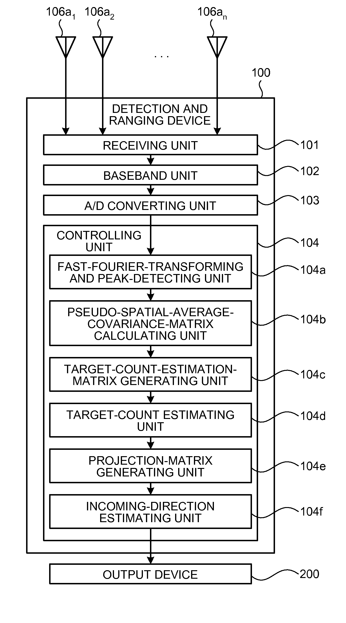
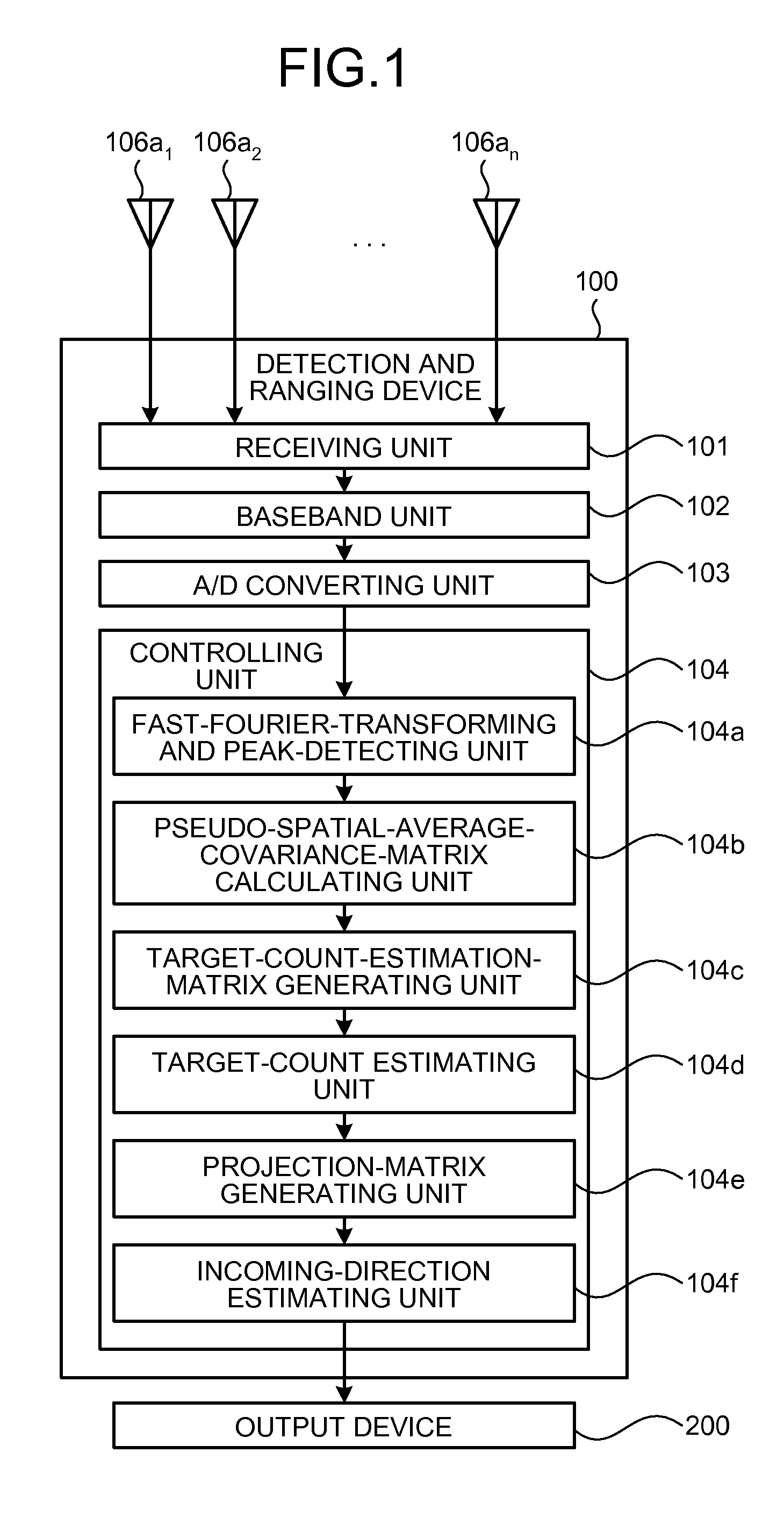
[0057]First, the configuration of the detection and ranging device according to an embodiment is explained. FIG. 1 is a functional block diagram of the configuration of the detection and ranging device according the embodiment. As depicted in FIG. 1, a detection and ranging device 100 according to the embodiment includes the sensor elements 106a1 to 106an equally spaced apart from each other so that a distance between adjacent sensor elements is d, a receiving unit 101 connected to the sensor elements 106a1 to 106an, a baseband unit 102, an analog / digital (A / D) converting unit 103, and a controlling unit 104.

[0058]The controlling unit 104 includes a fast-Fourier-transforming and peak-detecting unit 104a, a pseudo-spatial-average-covariance-matrix calculating unit 104b, a target-count-estimatio...


PUM


Abstract

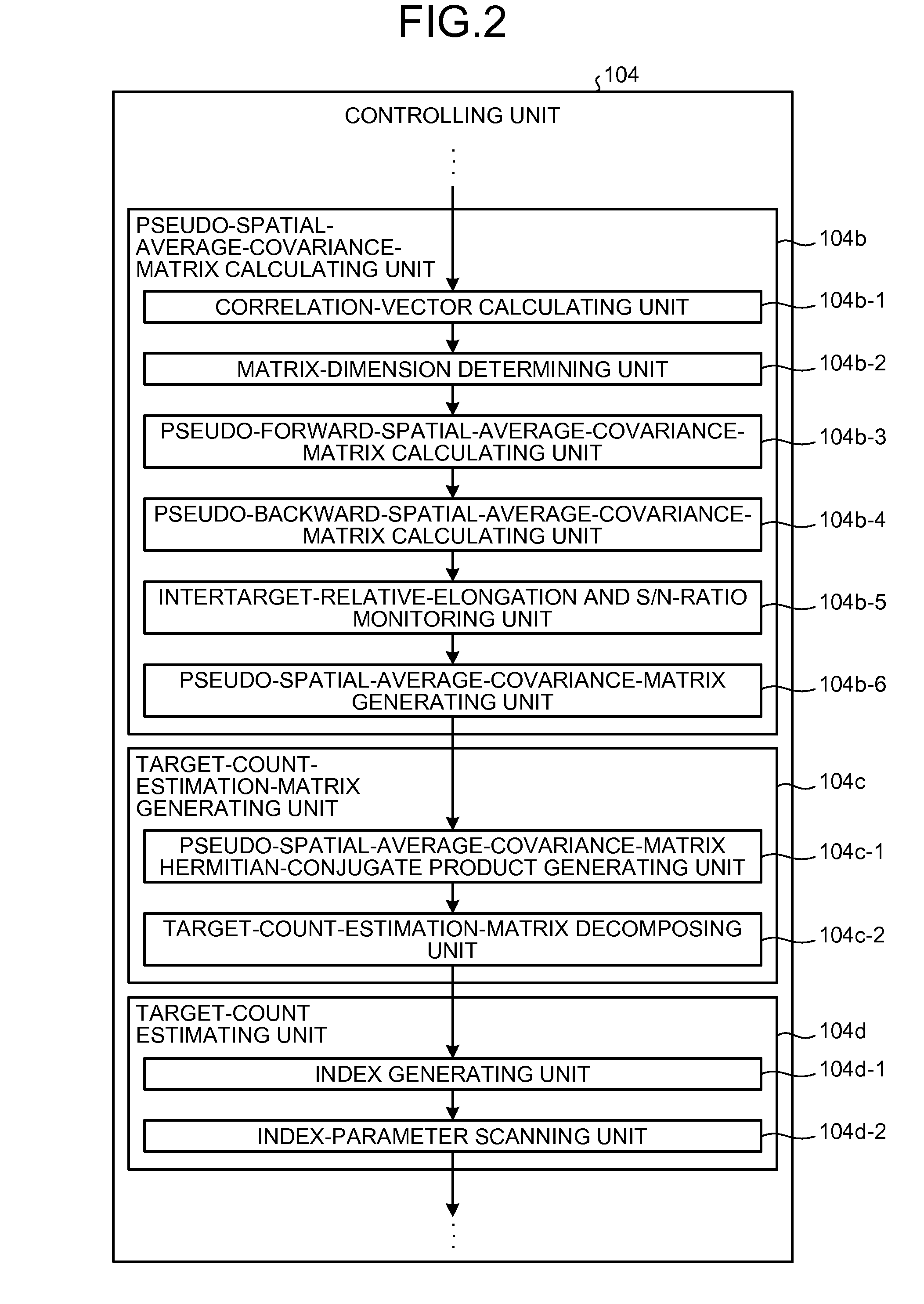
A pseudo-spatial-average-covariance-matrix generating unit selects, from matrixes Rf1, Rf2, Rb1 and Rb2, one appropriate matrix or two or more appropriate matrixes for combination to generate a pseudo-spatial-average-covariance matrix R. A pseudo-spatial-average-covariance-matrix Hermitian-conjugate product generating unit generates a target-count-estimation matrix RRH. A target-count-estimation-matrix decomposing unit performs LU decomposition on RRH into a lower triangular matrix L and an upper triangular matrix U. An index generating unit generates an index using elements of the upper triangular matrix U. An index-parameter scanning unit estimates a target count by using the index generated by the index generating unit.

Description

CROSS-REFERENCE TO RELATED APPLICATION[0001]This application is based upon and claims the benefit of priority of the prior Japanese Patent Application No. 2008-053506, filed on Mar. 4, 2008, the entire contents of which are incorporated herein by reference.BACKGROUND[0002]1. Field[0003]The present invention relates to a detection and ranging device and detection and ranging method with a transmission sensor array and a reception sensor array that is formed of n (2≦n) sensor elements, estimating a target count indicating the number of targets based on reflected signals of transmission signals sent from the transmission sensor array and reflected from the targets, and estimating an angle at which each reflected signal comes based on the target count.[0004]2. Description of the Related Art[0005]Conventionally, in a detection and ranging device having a sensor array formed of a plurality of sensor elements as a reception antenna to detect the target count and the position of each target...

Claims


Application Information

Patent Timeline
Patent Type & Authority Patents(United States)
IPC IPC(8): G01S13/00
CPCG01S3/74G01S7/35G01S13/48G01S13/42G01S13/931
Inventor SHIRAKAWA, KAZUO
Owner FUJITSU LTD
Learn More