Three-dimensional orientation indicator and controller

a controller and orientation indicator technology, applied in the field of three-dimensional (3d) graphics applications, can solve the problems of imposing a large amount of attention, difficult to access a number of views of data, and a large amount of model siz

Active Publication Date: 2010-08-24
AUTODESK INC
View PDF3 Cites 64 Cited by
  • Summary
  • Abstract
  • Description
  • Claims
  • Application Information

AI Technical Summary

Benefits of technology

[0038]To overcome the deficiencies of the prior art, one or more embodiments of the invention provide a special way of representing twenty-six (26) viewpoints through an interactive widget called the CubeCompass™. The CubeCompass™ is a 3D widget displayed in any corner of the 3D window that displays and controls the current viewpoint on the model compressing access to all twenty-six (26) viewpoints into a small space, and shows the spatial relationship between these views. On face views of the cube, additional controls appear that allow quick access to orthogonal viewpoints. Curved arrows allow viewpoint roll control. A home button returns the user to a standard three-quarter view.

Problems solved by technology

Accessing a number of views of the data is difficult and involves several user steps with prior art methods.
First, it clearly imposes highly divided attention, even for expert users.
Second, the main viewing area is quartered making the model much smaller, and so, harder to work with.
Third, there are many fixed-views sets which may be useful and the choice of which four to show may not be the best.
However, these users do not generally wish to invest much time into the significant learning and practice needed to operate complex 3D applications and their camera control techniques.
During their first encounters with 3D modeling applications, experienced 2D software users are often confused and misinterpret 3D scenes.
Thus, users are often confounded by their familiarity with 2D images (e.g., from a 2D graphics application such as Illustrator™ or Photoshop™) and have a difficult time understanding and realizing that there are hidden elements in the depth dimension.
However, such an approach is not concerned with desktop virtual environments operated with standard mouse and keyboard.
However, both engineering and architecture users have additional needs.
Such a multi-window display consumes screen space and divides attention resulting in multiple small work areas for the user.

Method used


Image

  • Three-dimensional orientation indicator and controller
  • Three-dimensional orientation indicator and controller
  • Three-dimensional orientation indicator and controller

Examples


Embodiment Construction

[0059]In the following description, reference is made to the accompanying drawings which form a part hereof, and which is shown, by way of illustration, several embodiments of the present invention. It is understood that other embodiments may be utilized and structural changes may be made without departing from the scope of the present invention.

Overview

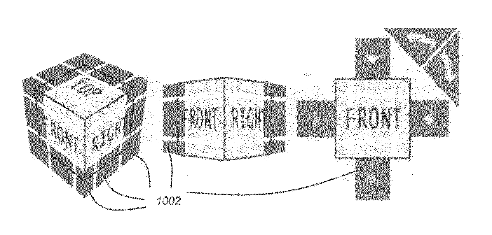
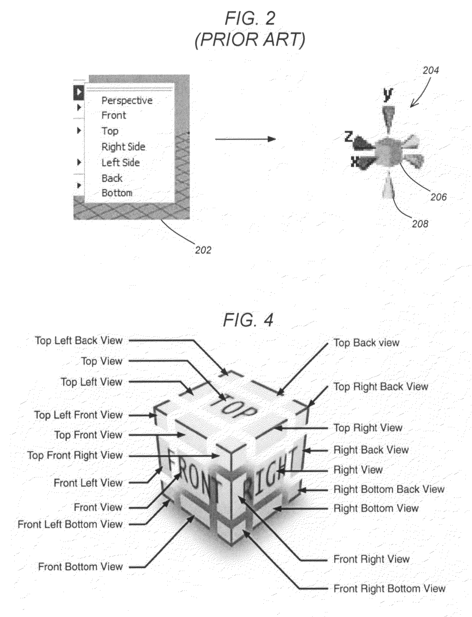
[0060]To address all of the problems and user requirements stated above, the present invention provides a small representation of the coordinate system that can be manipulated with multiple views per face. An example of such a coordinate system representation is the CubeCompass™ that consists of a cube shaped widget with selectable pieces that spatially arranges twenty-six possible views. In this regard, the CubeCompass™ allows the user to select a ¾ view, six main views (i.e., front, top, right side, left side, back and bottom), the edges of such views / faces, and the corners of the cube for a total of twenty-six (26) different views...


PUM


Abstract

A method, apparatus, and article of manufacture provide the ability to control a three-dimensional scene view. A three-dimensional (3D) scene having one or more three-dimensional objects is displayed. A 3D representation of a coordinate system of the scene is displayed. The 3D representation contains a current viewpoint, one or more faces, one or more edges, and one or more corners with each face, edge, and corner representing a corresponding viewpoint of the scene. The 3D representation is manipulated. A new current viewpoint of the 3D representation is displayed based on the manipulation. The scene is then reoriented corresponding to the new current viewpoint based on the manipulation of the 3D representation.

Description

CROSS-REFERENCE TO RELATED APPLICATIONS[0001]This application is related to the following co-pending and commonly-assigned patent application, which application is incorporated by reference herein:[0002]U.S. patent application Ser. No. 10 / 627,974, entitled “3D SCENE ORIENTATION INDICATOR SYSTEM WITH SCENE ORIENTATION CHANGE CAPABILITY”, by John Schrag and Takashi Watanabe, et. al., filed on Jul. 28, 2003.BACKGROUND OF THE INVENTION[0003]1. Field of the Invention[0004]The present invention relates generally to three-dimensional (3D) graphics applications, and in particular, to a method, apparatus, and article of manufacture for providing access to multiple views using a single orientation / controller widget.[0005]2. Description of the Related Art[0006](Note: This application references a number of different publications as indicated throughout the specification by reference numbers enclosed in brackets, e.g., [x]. A list of these different publications ordered according to these refer...

Claims


Application Information

Patent Timeline
Patent Type & Authority Patents(United States)
IPC IPC(8): G06T15/00G06T15/20
CPCG06F3/04815G06T15/20G06T19/00G06F2203/04802
Inventor GHOSH, ANIRBANMORDATCH, IGORKHAN, AZAMFITZMAURICE, GEORGE WILLIAMMATEJKA, JUSTIN FRANKSCHMIDT, RYAN M.KURTENBACH, GORDON P.
Owner AUTODESK INC
Why Eureka
Try Eureka