
Support frame for display and support structure for display having the same

a technology of supporting frame and display, which is applied in the direction of portable computer details, electrical apparatus casings/cabinets/drawers, instruments, etc., can solve the problems of metal interference, the frame cannot provide the fundamental function of reinforcing the lcd, and the radio wave reception rate of the antenna is deteriorated due to metal interference, etc., to improve the radio wave reception rate of the antenna, protect the liquid crystal display panel more effectively, and increase the strength of the support fram

Active Publication Date: 2010-08-24
LG ELECTRONICS INC
View PDF4 Cites 6 Cited by
  • Summary
  • Abstract
  • Description
  • Claims
  • Application Information

AI Technical Summary

Benefits of technology

The present invention aims to strengthen a display and improve the reception rate of an antenna. To achieve this, a support frame is provided that includes a seating portion, a connection portion, and a fastening portion. The connection portion allows an antenna to be inserted, while the fastening portion is supported by the case and protects the display panel. The support frame has an escape portion that allows the antenna to be exposed, and a reinforcing rib is provided between the insertion hole and the escape portion. The support frame is connected to a base plate and a connection terminal protrudes from the seating portion to connect to the base plate. This invention makes the display more durable and improves the reception of radio waves.

Problems solved by technology

However, the above prior art has the following problems.
At this time, if the antenna is mounted near the LCD, a radio wave reception rate of the antenna is deteriorated due to the frame.
It is because the frame made of metal interferes with the reception or transmission of a radio wave.
However, in such a case, the frame cannot provide its fundamental function of reinforcing the LCD.

Method used


Image

  • Support frame for display and support structure for display having the same
  • Support frame for display and support structure for display having the same
  • Support frame for display and support structure for display having the same

Examples


Embodiment Construction

[0025]Hereinafter, a preferred embodiment of the present invention will be described in detail with reference to the accompanying drawings.

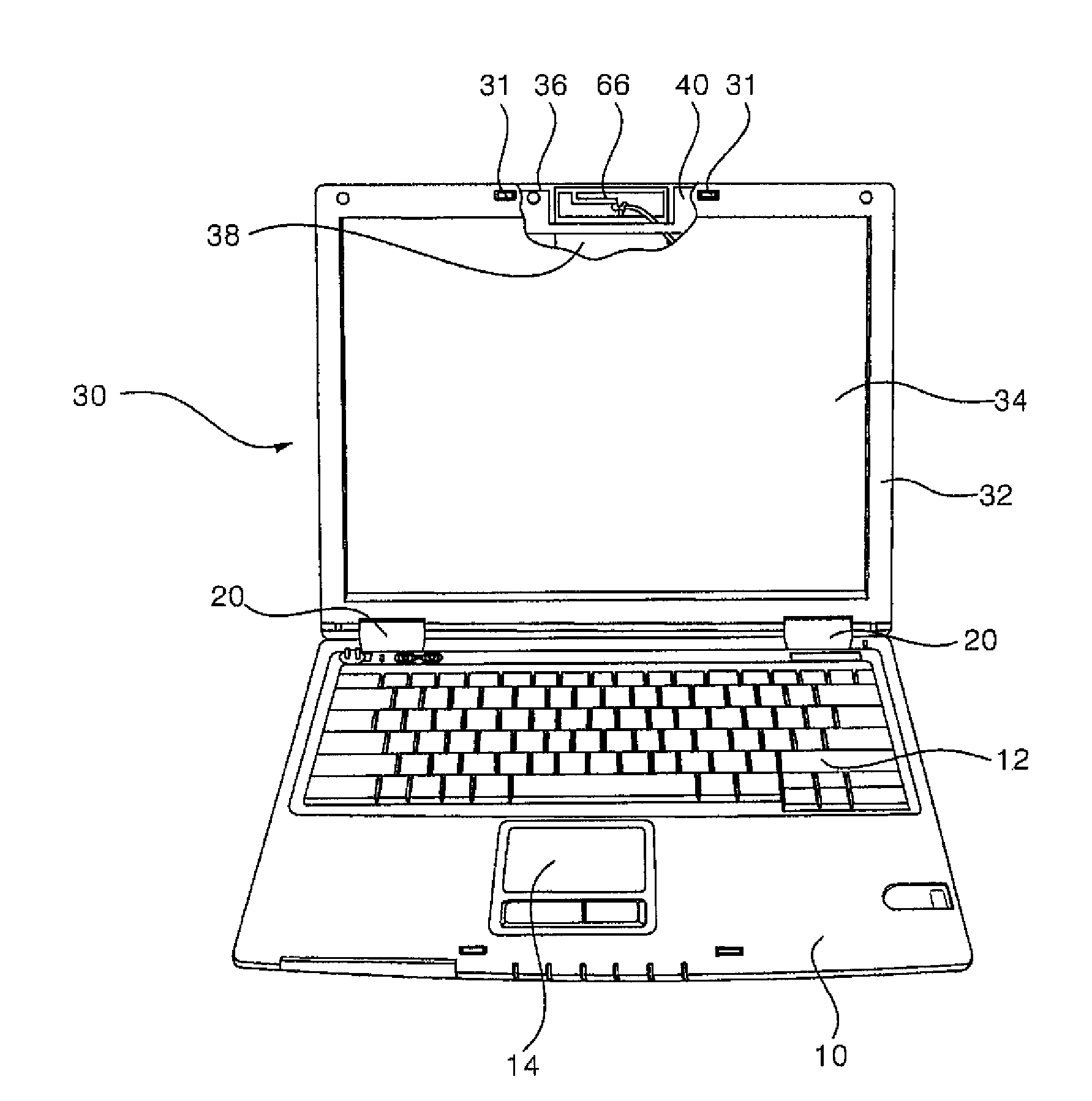
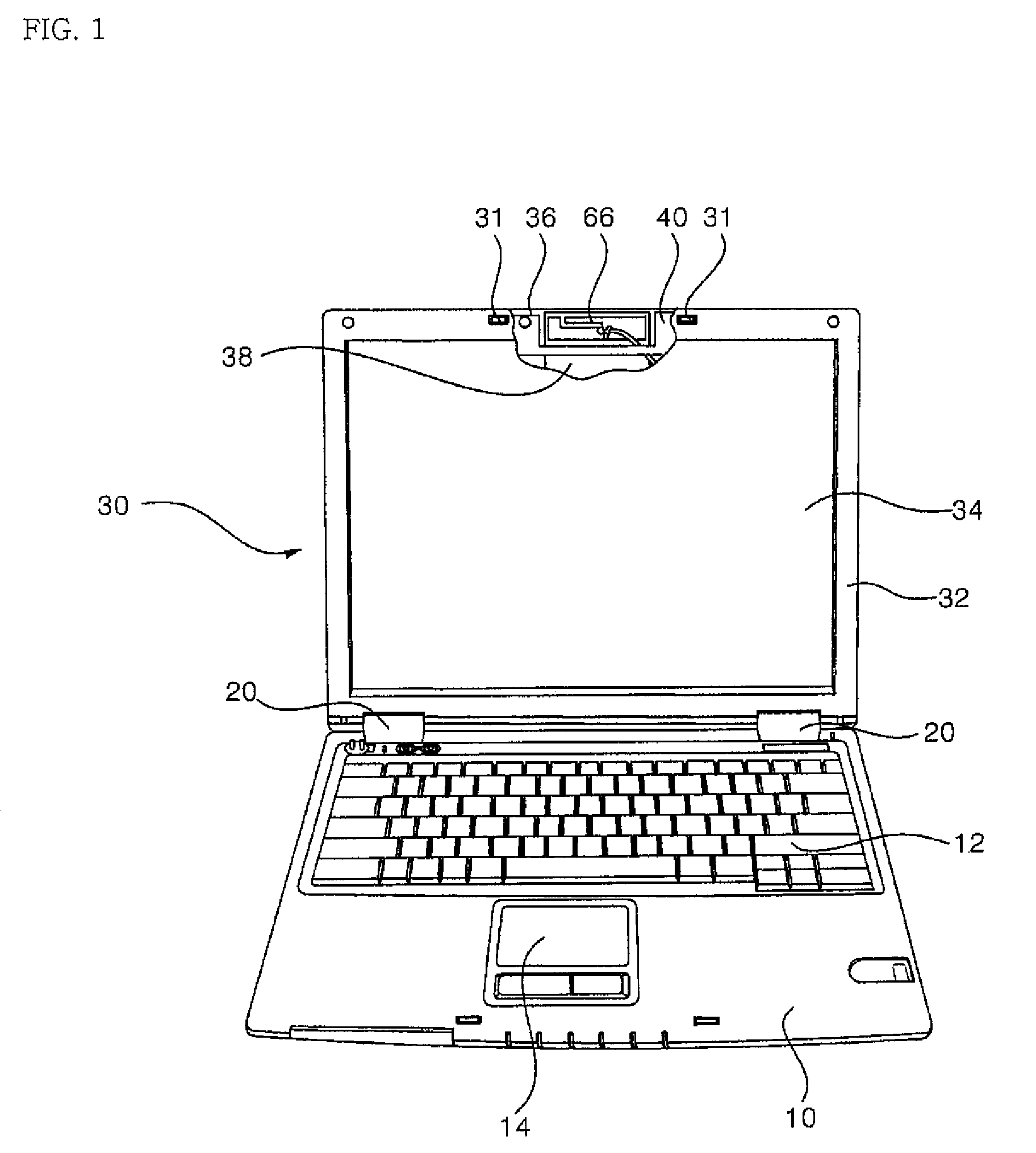
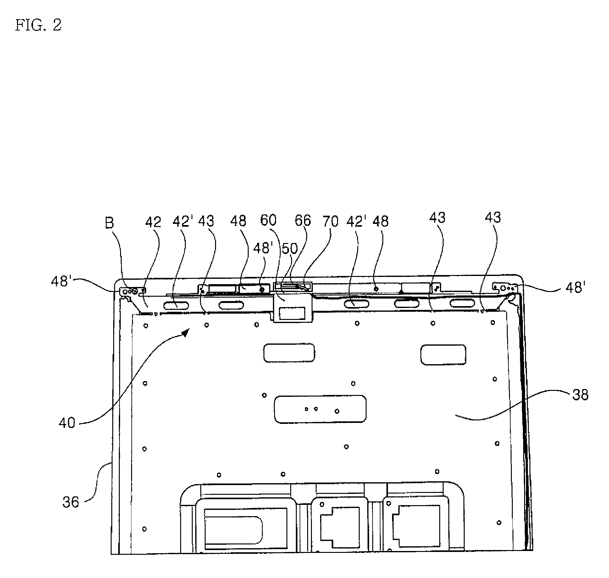
[0026]FIG. 1 is a partially sectioned perspective view showing a portable computer to which a support frame for a display according to the present invention is applied, FIG. 2 is a front view showing an interior of a portable computer to which a support structure for a display according to the present invention is applied, FIG. 3 is a perspective view showing a major portion of a case and a support frame provided therein according to the present invention, FIG. 4 is a perspective view showing a major portion in which an antenna is coupled to the support structure for a display according to the present invention, and FIG. 5 is a perspective view showing a major portion in which a liquid crystal display panel is coupled to the support structure according to the present invention.

[0027]According to the figures, a main body 10 has a generally flat he...


PUM


Abstract

The present invention relates to a support frame for a display and a support structure for a display having the support frame. A support frame for a display of the present invention comprises a seating portion 42 seated on a bottom surface of a case 36; a connection portion 45 extending perpendicularly from the seating portion 42 and having an insertion hole 47 into which an antenna 60 is inserted; and a fastening portion 48 extending perpendicularly from the connection portion 45 and supported by one side of the case 36. According to the present invention so configured, it is possible to increase the strength of the support frame and thus protect a liquid crystal display panel more effectively by means of the reinforcing rib 50 and the escape portion 49 provided in the support frame, and also to improve a radio wave reception rate of the antenna 60.

Description

BACKGROUND OF THE INVENTION[0001]1. Field of the Invention[0002]The present invention relates to a portable electronic device, and more particularly, to a support frame for supporting a display of a portable electronic device with an antenna, and a support structure for a display having the support frame.[0003]2. Description of the Related Art[0004]Recently, a variety of portable electronic devices such as a portable computer provided with an antenna for receiving wireless Internet or digital multimedia broadcasting (DMB) are put into the market. Such a portable electronic device is generally provided with a liquid crystal display (LCD). In case of a device, such as a portable computer, which has a relatively large volume and has such an LCD occupying a large region, there is provided an additional frame for protecting the LCD.[0005]Also, a portable electronic device includes an antenna therein to access the wireless Internet or receive DMB. The antenna generally includes a film ant...

Claims


Application Information

Patent Timeline
Patent Type & Authority Patents(United States)
IPC IPC(8): G06F1/16H04B1/38H04M1/00H01L35/00H10N10/00
CPCG06F1/1616G06F1/1698G06F1/1679G06F1/1637H01R13/46G06F2200/161
Inventor CHO, JAE-MAN
Owner LG ELECTRONICS INC
Learn More