Multiple tube pulse detonation engine turbine apparatus and system

a turbine and multi-tube technology, applied in the field of pulse detonation engines, can solve the problems of multiple mechanical assembly and alignment challenges of multi-chamber pde, and achieve the effect of facilitating fuel injection and ignition

Active Publication Date: 2010-08-31
GENERAL ELECTRIC CO
View PDF42 Cites 27 Cited by
  • Summary
  • Abstract
  • Description
  • Claims
  • Application Information

AI Technical Summary

Problems solved by technology

However, with this newer configuration, several mechanical assembly and alignment challenges for the multi-chamber PDE are also presented.

Method used


Image

  • Multiple tube pulse detonation engine turbine apparatus and system
  • Multiple tube pulse detonation engine turbine apparatus and system
  • Multiple tube pulse detonation engine turbine apparatus and system

Examples


Embodiment Construction

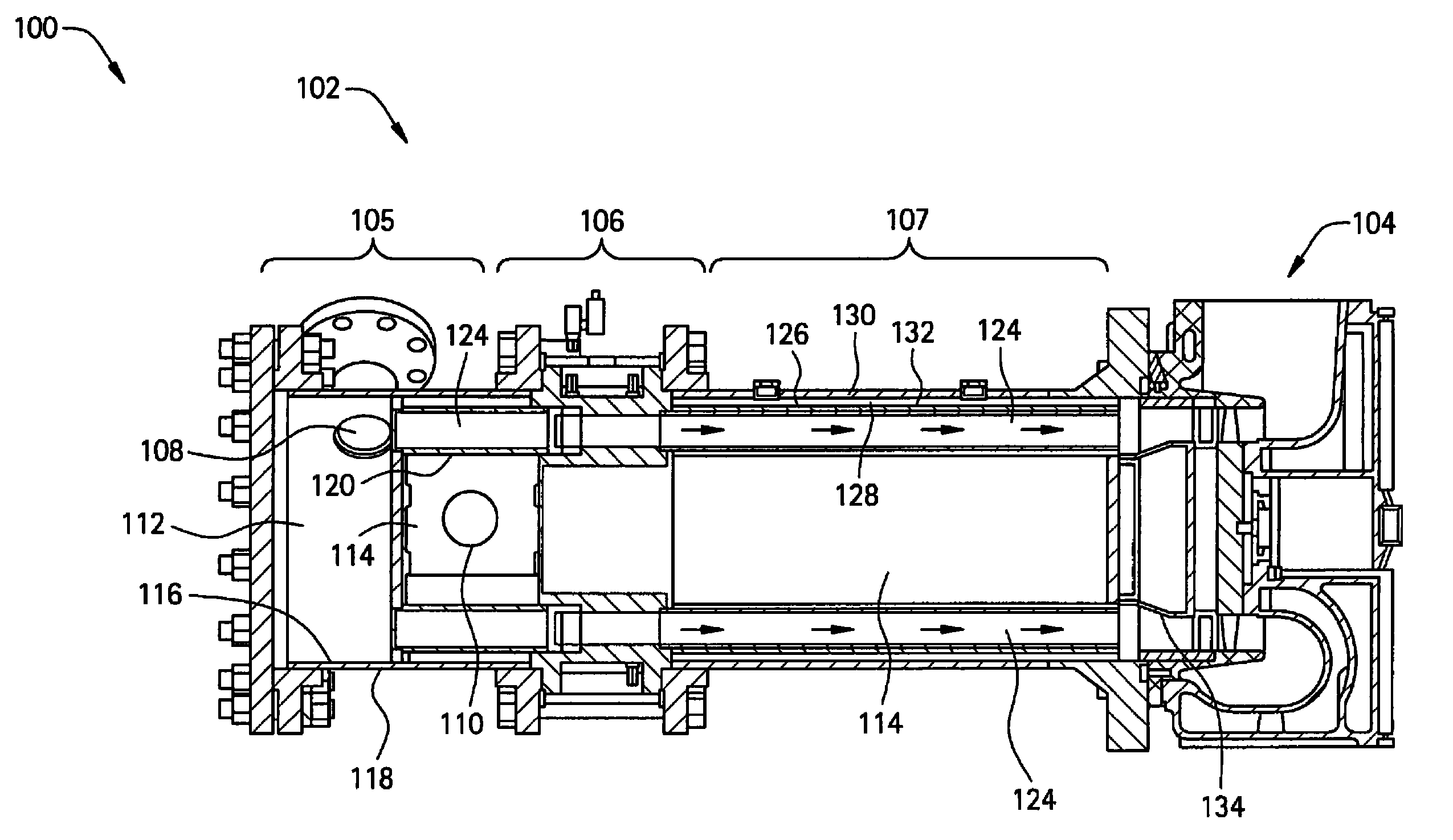
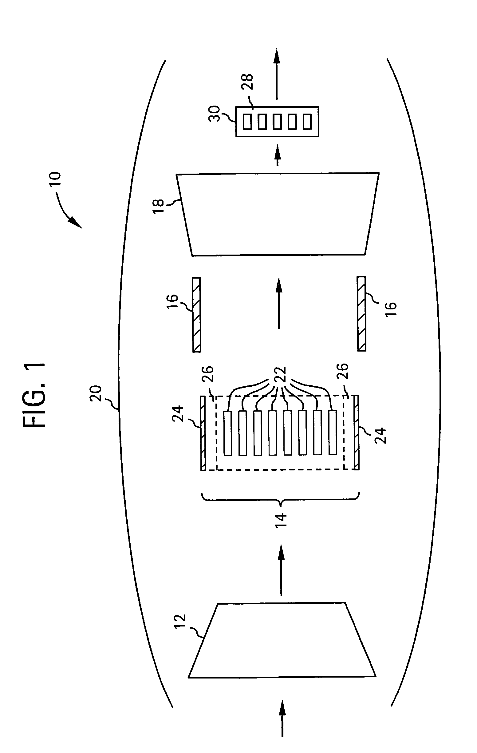
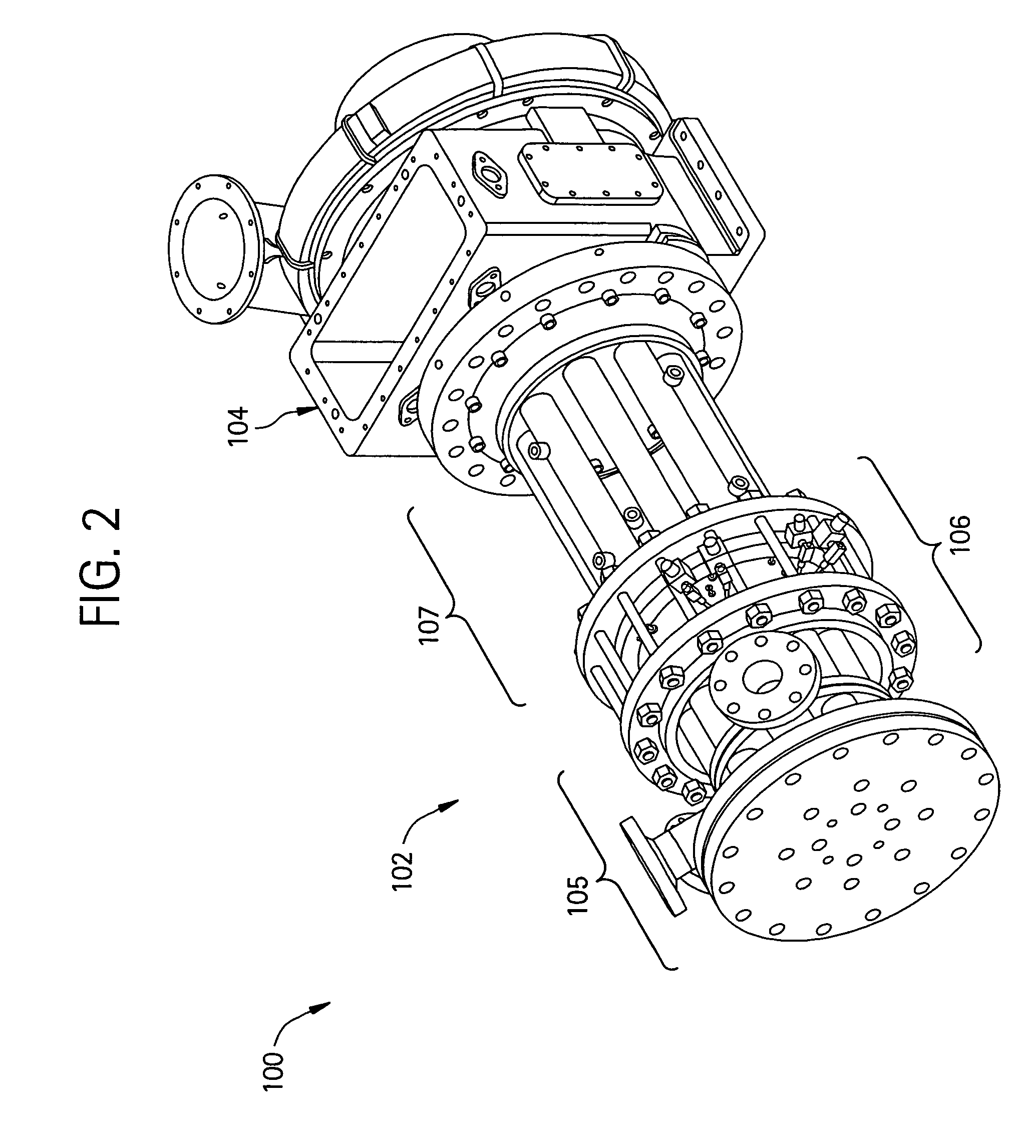
[0017]Disclosed herein are pulse detonation engines and improved components of the same. As will be discussed in greater detail, the pulse detonation engine generally comprises a pulse detonation combustor located within a coaxial liner that allows the pulse detonation combustor to be cooled, (optionally) a transition piece located downstream of the pulse detonation combustor configured to direct flow from the combustor and coaxial liner to an axial turbine assembly located downstream, and (optionally) a axial turbine assembly. A source of a compressed oxidizer (e.g., a compressor) is located upstream of the pulse detonation combustor.

[0018]In the descriptions that follow, the term “axial” refers broadly to a direction parallel to the axis about which the rotating components of a gas turbine engine rotate. An “upstream” direction refers to the direction from which the local flow is coming, while a “downstream” direction refers to the direction in which the local flow is traveling. I...


PUM


Abstract

A pulse detonation combustor (PDC) assembly includes an upstream chamber forming an inlet plenum, a downstream chamber including a downstream portion of at least one PDC tube, and an integrated PDC head coupled to the upstream chamber and the downstream chamber. The integrated PDC head is configured to facilitate fuel injection and ignition within the PDC tube. The PDC tube includes an inner seal surface and an outer seal surface configured to mate with the inner seal surface, wherein the inner seal surface includes an elevated section thereon that engages with the outer seal surface such that the PDC tube is free to partially pivot about a longitudinal axis thereof.

Description

BACKGROUND OF THE INVENTION[0001]The present disclosure relates generally to a pulse detonation engine (PDE) and, more particularly, to a multiple tube pulsed detonation chamber (PDC).[0002]Known pulse detonation engines generally operate with a detonation process having a pressure rise, as compared to engines operating within a constant pressure deflagration. Although such engines vary in their implementation, a common feature is that air flow is directed into one or more pulse detonation chambers wherein the air is mixed with fuel and ignited to produce a combustion pressure wave. The combustion wave transitions into a detonation wave followed by combustion gases that produce thrust as they are exhausted from the engine. As such, pulse detonation engines may have the potential to operate at higher thermodynamic efficiencies than may generally be achieved with deflagration-based engines.[0003]At least some known hybrid pulse detonation-turbine engines have replaced the steady flow ...

Claims


Application Information

Patent Timeline
Patent Type & Authority Patents(United States)
IPC IPC(8): F02C5/00
CPCF02C5/00F02C5/10F23R7/00F05D2220/326F05D2220/327
Inventor RASHEED, ADAMDEAN, ANTHONY JOHN
Owner GENERAL ELECTRIC CO
Why Eureka
Try Eureka