Fuel leakage preventing valve

a technology of fuel leakage prevention and valve seat, which is applied in the direction of functional valve types, transportation and packaging, containers, etc., can solve the problems of affecting the sealing property of the valve, the valve seat cannot be closed by the float valve, and the valve closing characteristics can vary, so as to avoid the rattling of the valve body, the valve sealing property is reliable, and the valve seat is not affected.

Active Publication Date: 2010-08-31
PIOLAX CO LTD +1
View PDF6 Cites 12 Cited by
  • Summary
  • Abstract
  • Description
  • Claims
  • Application Information

AI Technical Summary

Benefits of technology

[0026]In the third aspect of the present invention, since the height of the protruding step portion of the float valve is larger than the thickness of the flange portion of the retainer, any fuel tending to gather is drained over a wide range from the accommodating space such that it can be quickly discharged.
[0032]In the ninth or sixteenth aspect of the present invention, the valve body is formed as the integral unit composed of the upper layer portion of elastomer and the lower layer portion of metal or resin, with the protrusion for promoting rocking of the valve body being provided on the lower surface of the lower layer portion, so the valve body itself does not easily swell. Further, while there is a fear of the surface of the protruding step portion of the float valve being scraped by the protrusion of the lower layer portion, the scraping does not occur in a uniform fashion, so it is possible to maintain the rocking motion of the valve body for a long period of time.

Problems solved by technology

However, in the conventional fuel leakage preventing valve, in which the float valve is composed of the two components of the outer float and the inner float, fuel is likely to gather between the outer float and the inner float, that is, in the space where the valve plate is held.
With some fuel accumulated, the float valve itself is subjected to a weight from the fuel so much that it may be impossible for the float valve to close the valve seat with its valve plate unless the liquid level is high.
Thus, these cause a fear of variations in valve closing characteristics.
This involves a fear of the sealing property becoming unstable, thus, in any case, conventional fuel leakage preventing valves have merits and demerits.

Method used


Image

  • Fuel leakage preventing valve
  • Fuel leakage preventing valve
  • Fuel leakage preventing valve

Examples


embodiment 1

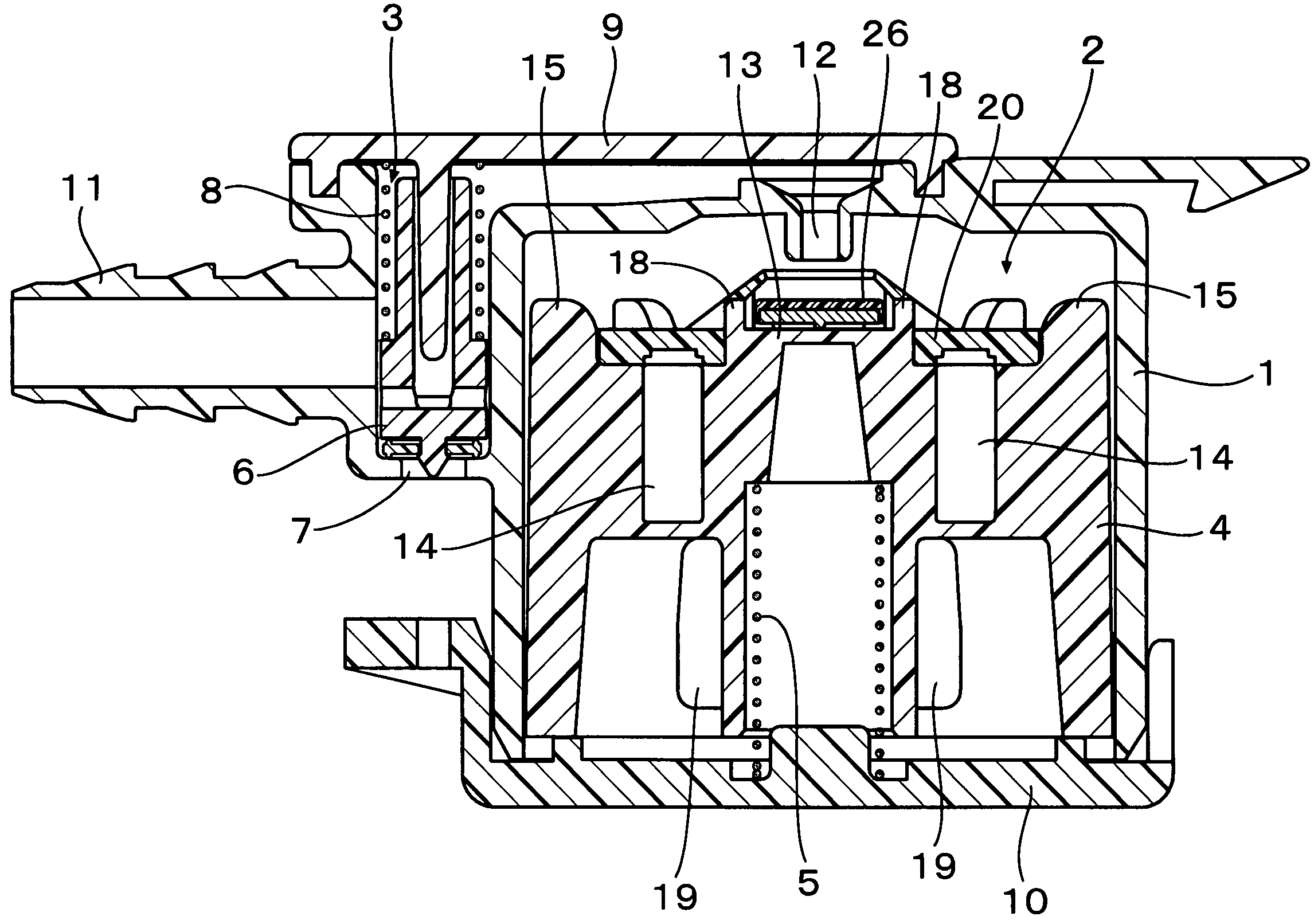
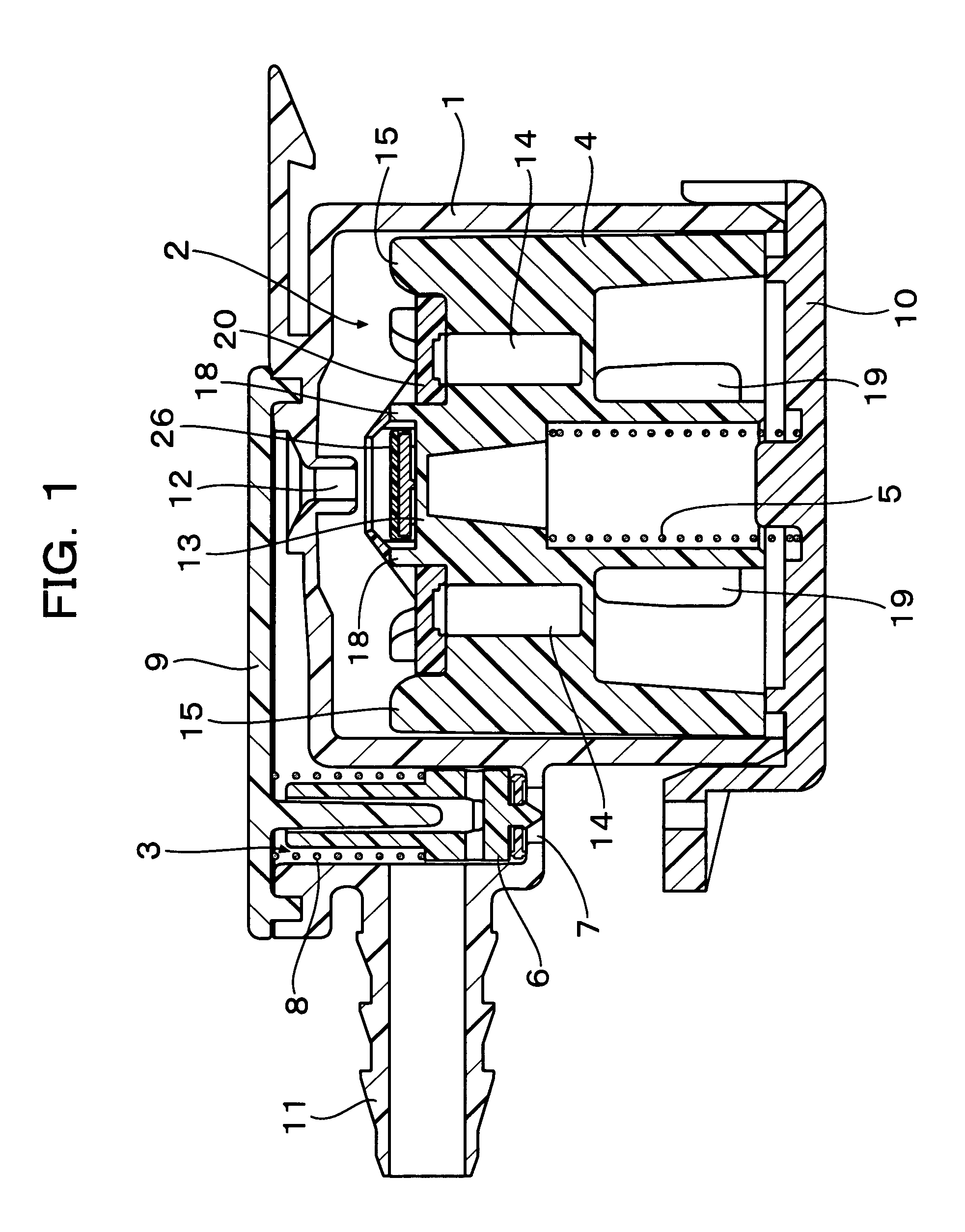
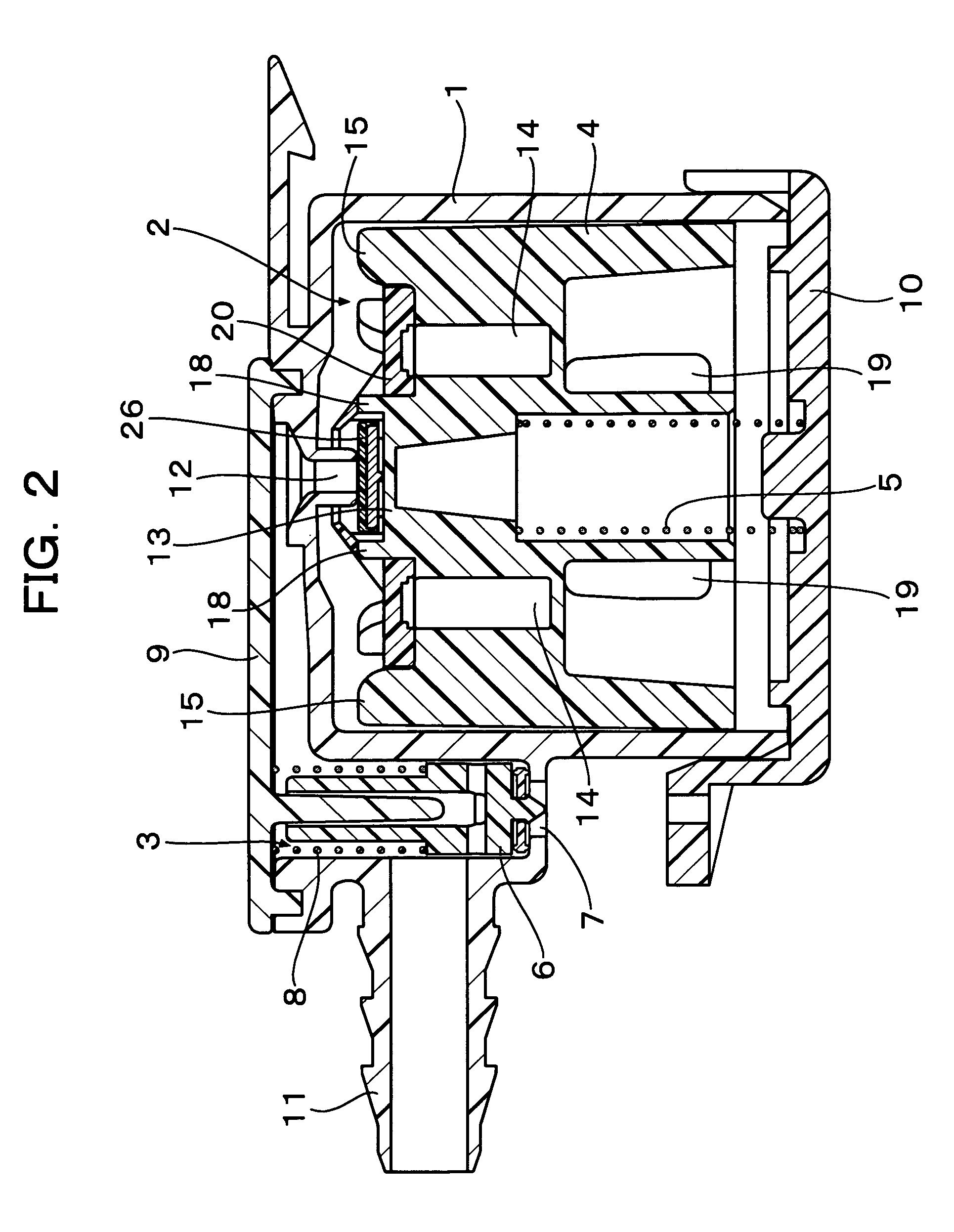
[0053]First, as shown in FIGS. 1 and 2, in a fuel leakage preventing valve according to Embodiment 1, within a housing 1 constituting the base body thereof, there are independently defined a float valve chamber 2 and a relief valve chamber 3. In the former, that is, in the float valve chamber 2, a float valve 4 to which a retainer 20 described below is welded is arranged so as to be vertically movable, with the float valve 4 being upwardly urged by the pressure of a spring 5. In the latter, that is, in the relief valve chamber 3, a relief valve 6 is arranged so as to be vertically movable, and an exhaust port 7 is formed in the partition wall of the relief valve chamber 3 so as to communicate with a fuel tank, with the exhaust port 7 being normally closed with the pressure of a spring 8. Numeral 9 indicates an upper cap attached to the upper side of the housing 1, and numeral 10 indicates a lower cap attached to the lower side of the housing 1.

[0054]As shown also in FIG. 3, in the h...

embodiment 2

[0071]Next, a fuel leakage preventing valve according to Embodiment 2 will be described. While in Embodiment 1 fuel is passed through the communication holes 25 and discharged to the outside from the upper surface of the flange portion 21 of the retainer 20, Embodiment 2 adopts a construction in which, as shown in FIGS. 10 and 11, four communication paths 28 are radially formed to extend from the inner surface of the cage portion 22 of the retainer 20 along the lower surface of the flange portion 21, thus establishing communication between the accommodating space 23 and the outside through the communication paths 28.

[0072]As shown in FIG. 12, the retainer 20 is assembled to the float valve 4 such that the four radial communication paths 28 are arranged between the plurality of guide ribs 15 formed at equal intervals in the outer periphery of the float valve 4. Further, as shown in FIG. 12, in the upper end portions of the protruding rim 16, cut-out portions 16a situated at the forwa...


PUM


Abstract

Disclosed is a fuel leakage preventing valve, involving no variations in valve closing characteristics, in which a vertically movable float valve is arranged in a chamber defined inside a housing and in which a valve seat of the housing communicating with an outside is opened and closed by the float valve, which has a protruding step portion formed upwardly at the center of an upper surface of the float valve, a retainer fixed to the upper surface side of the float valve, the retainer having a flange portion covering the upper surface of the float valve and a cage portion raised from the flange portion to define an accommodating space in conjunction with the protruding step portion of the float valve; and a valve body for opening and closing the valve seat of the housing is rockably accommodated in the accommodating space defined by the cage portion.

Description

BACKGROUND OF THE INVENTION[0001]1. Field of the Invention[0002]The present invention relates to a fuel leakage preventing valve for preventing fuel leakage from a fuel tank at the time, for example, of cornering or rolling-over of an automobile.[0003]2. Description of the Related Art[0004]In a conventional fuel preventing valve, an accommodating chamber is defined inside a housing, and a float valve composed of an outer float and an inner float is arranged in the accommodating chamber so as to be vertically movable. The float valve is upwardly urged by the pressure of a spring, and a valve seat is formed on an upper partition wall side of the accommodating chamber of the housing, with the valve seat being opened and closed by a valve plate held by the float valve. As disclosed, for example, in JP 2003-120449A (corresponding to U.S. Pat. No. 6,508,263), the relationship between the outer float and the inner float of the float valve is as follows: the outer float has on its upper por...

Claims


Application Information

Patent Timeline
Patent Type & Authority Patents(United States)
IPC IPC(8): F16K24/04
CPCF16K24/044Y10T137/0874Y10T137/3099
Inventor FURUYA, MASASHI
Owner PIOLAX CO LTD
Why Eureka
Try Eureka