Connector

Active Publication Date: 2010-08-31
YAZAKI CORP
View PDF14 Cites 4 Cited by
  • Summary
  • Abstract
  • Description
  • Claims
  • Application Information

AI Technical Summary

Benefits of technology

[0012]It is therefore an objective of the present invention to solve the above problem and to provide a connector, which prevents liquid such as water from entering the body part that receives the terminal fitting therein so that the liquid such as water is prevented from adhering on the terminal fitting and so on.
[0021]With the construction described above, when liquid such as water enters from between the hood part of the first connector housing and the tube part of the second connector housing, the liquid such as water can be smoothly drained from the through hole to the outside. Therefore, the liquid such as water can be prevented from entering in between the hood part of the first connector housing and the body part of the second connector housing. Accordingly, the liquid such as water can be prevented from entering the body part, which receives the terminal fittings, and therefore, the liquid such as water can be prevented from adhering on the terminal fitting and so on.
[0023]With the construction described above, even when liquid such as water, which is entered in between the hood part of the first connector housing and the tube part of the second connector housing, is not fully drained and remains at the connecting part, the liquid such as water can be prevented from entering in between the hood part and the body part from an end part of the hood part. Accordingly, the liquid such as water can be securely prevented from entering the body part, which receives the terminal fittings, and therefore, the liquid such as water can be securely prevented from adhering on the terminal fitting and so on.

Problems solved by technology

However, the simple waterproof connector described above has a problem that when a side surface of the body part of the female housing is provided with a restricting member-receiving part, into which a restricting member for preventing the female terminal received in the body part of the female housing from coming out is inserted, there is a possibility that liquid such as water enters the body part from the restricting member-receiving part, causing a problem that the liquid such as water entered the body part of the female housing might adhere on the terminal fitting and so on.

Method used


Image

  • Connector
  • Connector
  • Connector

Examples


Embodiment Construction

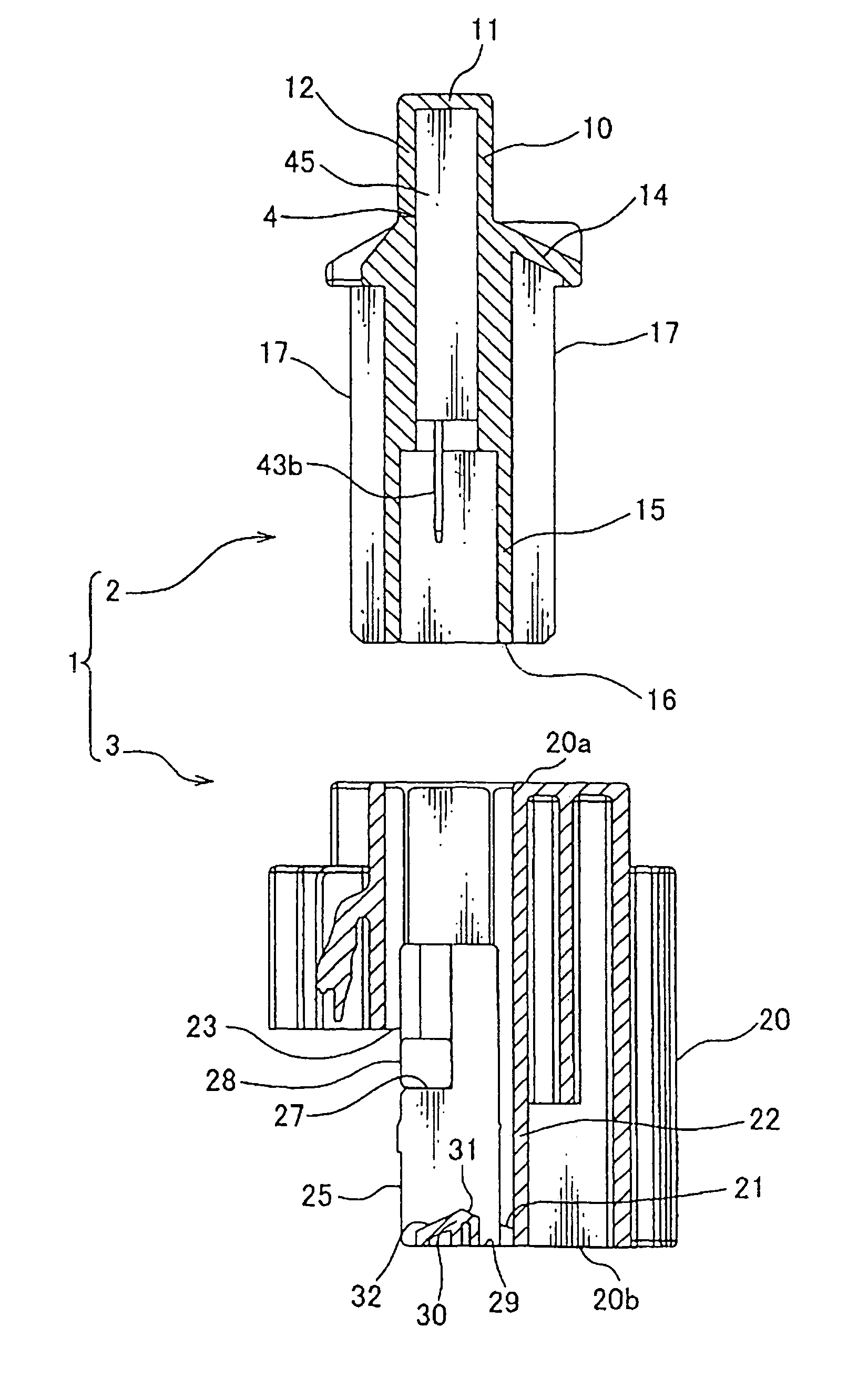
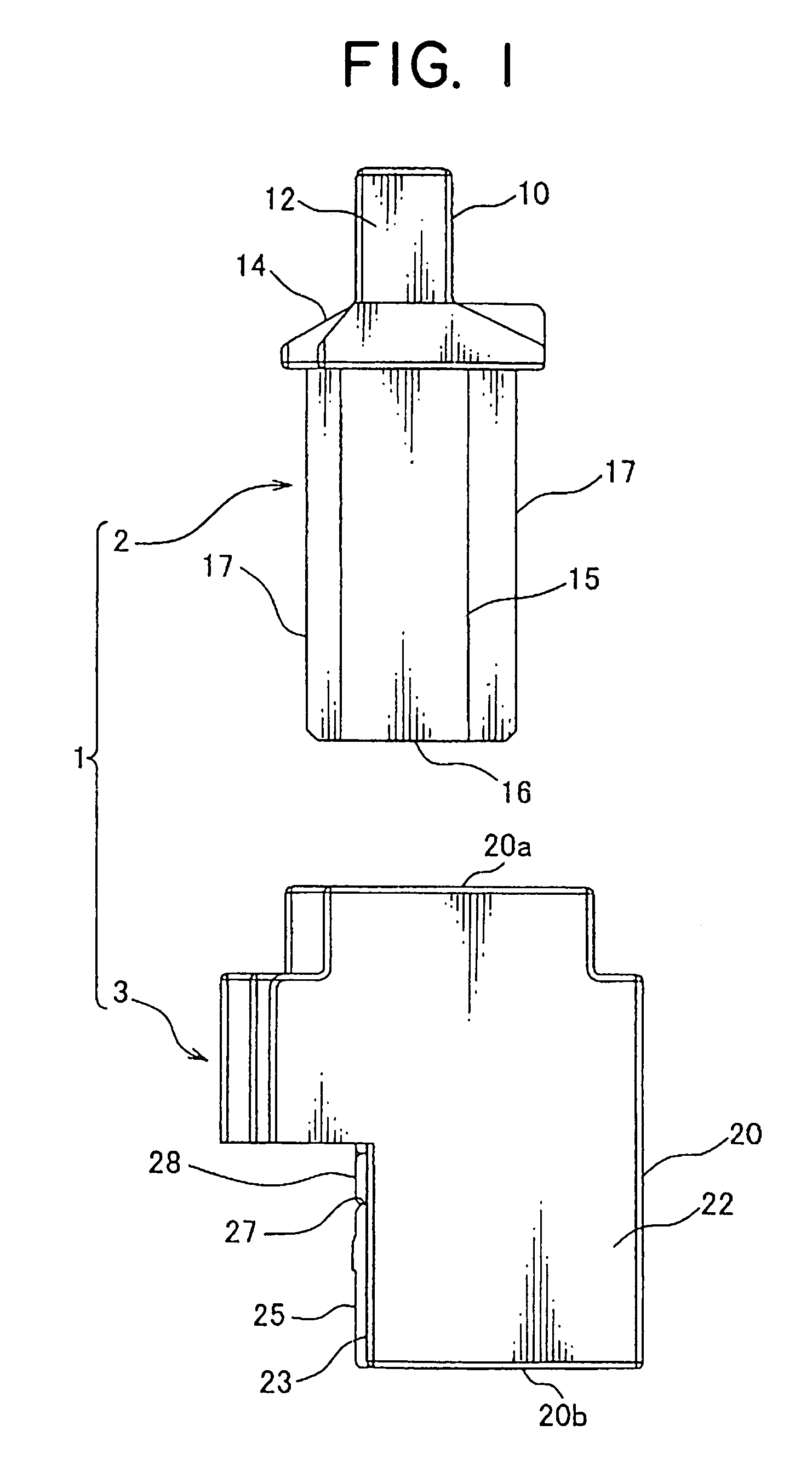
[0030]In the following, a preferred embodiment of the present invention will be explained with reference to FIGS. 1-6. As shown in FIG. 1, a connector 1 according to the preferred embodiment of the present invention includes a male connector housing 2 (hereinafter, male housing 2) and a female connector housing 3 (hereinafter, female housing 3).

[0031]The male housing 2 corresponds to the first connector housing described above and the female housing 3 corresponds to the second connector housing described above.

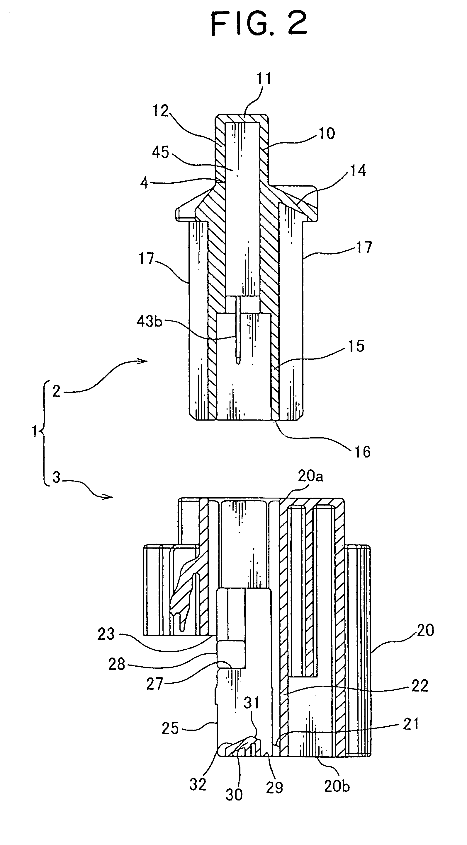
[0032]The male housing 2 is made of electrically insulating synthetic resin or the like and as shown in FIG. 1, includes a receiving part 10 and a tube-shaped hood part 15 continuing to the receiving part 10. As shown in FIG. 2, the male housing 2 receives a switching unit 4 therein.

[0033]As shown in FIG. 6, the switching unit 4 includes a unit body 40 and a resin sealing body 45 encircling the unit body 40. The unit body 40 includes a circuit board 41, a switching device 42 m...


PUM


Abstract

The connector including the first and second connector housings is provided with means for draining water entered inside. At an end part of the second connector housing, situated at the front of an insertion direction of the first connector housing into the second connector housing, the second connector housing includes: a connecting part which connects a tube part and a body part of the second connector housing to each other; and a through hole which is adjacent to the connecting part and penetrates through the tube part to communicate a first space, which is outside the body part and inside the tube part, and the outside of the tube part to each other, wherein a facing surface of the connecting part facing the first connector housing is provided with an inclined surface gradually inclining toward the insertion direction as the facing surface approaches the through hole.

Description

BACKGROUND OF THE INVENTION[0001](1) Field of the Invention[0002]The present invention relates to a connector for use in connection of electric wires and particularly to a connector including a drain means for draining water entered inside.[0003](2) Description of the Related Art[0004]Various electronic instruments are mounted on a motor vehicle as a mobile unit. A wiring harness is arranged in the motor vehicle to transmit electric power and control signals to the electronic instruments. The electronic instrument and the wiring harness are connected to each other when connectors thereof are fitted to one another.[0005]The connector includes a connector housing and terminal fittings to be received in the connector housing. When the connectors are fitted to each other, the terminal fittings in the respective connector housings are electrically connected to one another.[0006]As for the connector described above, a simple waterproof connector (see Japanese Patent Application Laid-Open ...

Claims


Application Information

Patent Timeline
Patent Type & Authority Patents(United States)
IPC IPC(8): H01R13/627
CPCH01R13/46H01R13/5227H01R13/631
Inventor ITO, YOSHITAKAKODAMA, SHINJI
Owner YAZAKI CORP
Why Eureka
Try Eureka