Eureka AIR delivers breakthrough ideas for toughest innovation challenges, trusted by R&D personnel around the world.

Suspension bend section with stiffness-reducing features

a technology of suspension bend section and feature, applied in the direction of magnetic recording, data recording, instruments, etc., can solve the problems of reducing sway stiffness and torsional stiffness, reducing resonant performance, and reducing track following performance, so as to reduce the vertical stiffness of the preload bend section

Active Publication Date: 2010-08-31
SEAGATE TECH LLC
View PDF15 Cites 5 Cited by
  • Summary
  • Abstract
  • Description
  • Claims
  • Application Information

AI Technical Summary

Benefits of technology

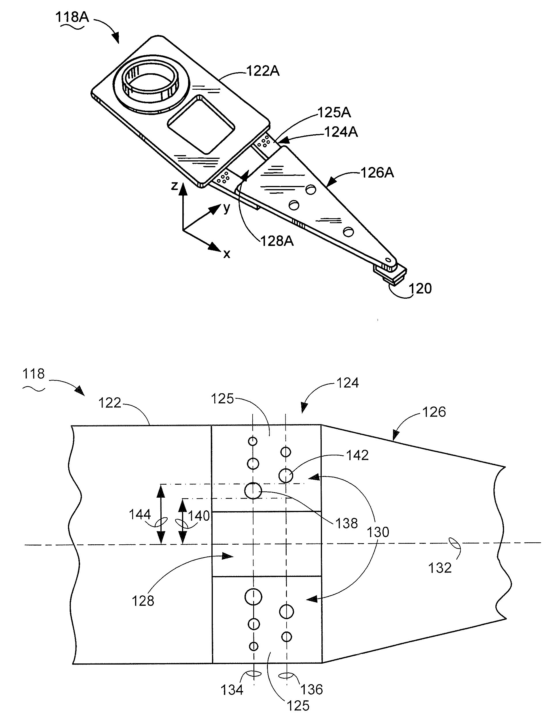
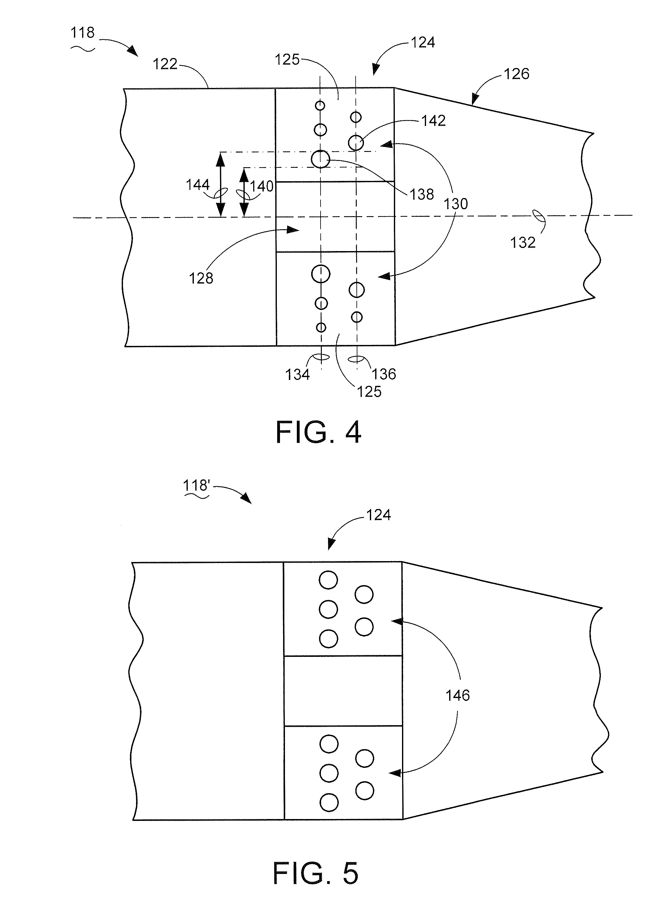
[0008]A data storage device is provided comprising an actuator in combination with a data storage medium, and means for positioning the actuator in an operable data storing and data retrieving relationship with the data storage medium. The means for positioning can be characterized by reducing the vertical stiffness of a preload bend section of the actuator in an array of stiffness-reducing features. The means for positioning can further be characterized by varying the sizes and locations of the stiffness-reducing features. The means for positioning can further be characterized by sequentially sizing the stiffness-reducing features from largest to smallest with the largest being disposed nearest a centerline of the actuator at the preload bend section. Similarly, a cross section may be constructed in which the thinnest area is near the center line and the thickness increases toward the outer edges.

Problems solved by technology

However, the vertical stiffness cannot be achieved at the cost of reducing resonant performance, resulting in reduced track following performance.
Particularly, reducing the material bend strength of the bend section aids in reducing the vertical stiffness, but disadvantageously also reduces the sway stiffness and torsional stiffness, resulting in resonant frequency disturbances.

Method used


Image

  • Suspension bend section with stiffness-reducing features
  • Suspension bend section with stiffness-reducing features
  • Suspension bend section with stiffness-reducing features

Examples


Embodiment Construction

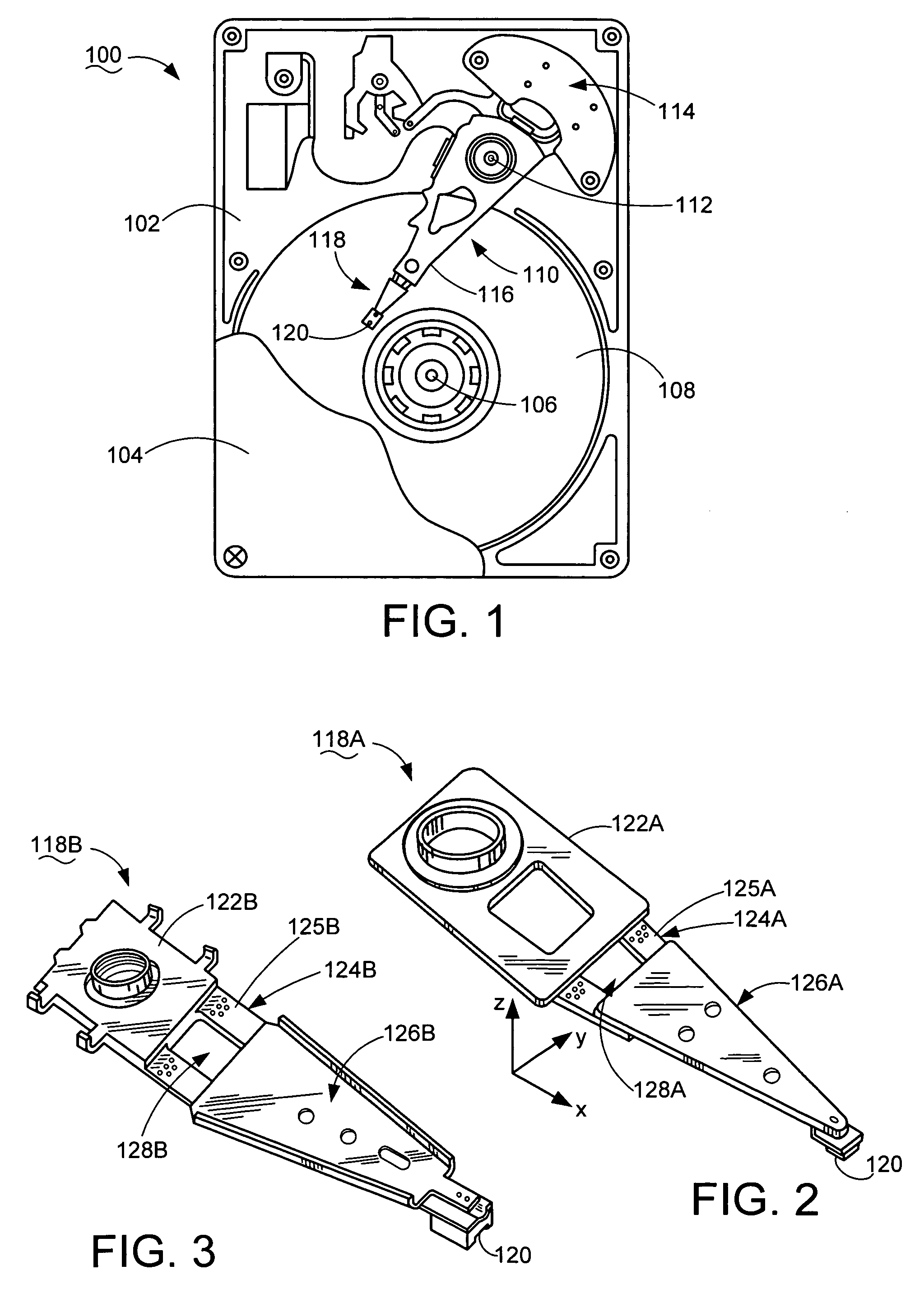
[0016]Turning to the drawings as a whole and particularly now to FIG. 1 which is a plan view of a data storage device 100 constructed in accordance with embodiments of the present invention. The data storage device 100 has a base 102 to which a cover 104 (partially cutaway) is attached with a sealing member therebetween to establish a sealed enclosure.

[0017]A spindle motor 106 is mounted to the base 102 for rotating one or more data storage mediums (“discs”) 108. An actuator, such as a rotary actuator 110, has a central body (or “eblock”) supported by the base 102 around a bearing 112 and pivotally moved by a voice coil motor 114. The actuator 110 has one or more rigid arms 116 extending from the body and supporting a proximal end of a flexible suspension assembly 118. The distal end of the suspension assembly 118 supports a head 120 having data storing and retrieving elements, as well as a slider assembly for flying the head 120 on a fluid bearing created by spinning the discs 108....


PUM

PropertyMeasurementUnit
diametersaaaaaaaaaa
resonant frequencyaaaaaaaaaa

Abstract

An actuator load beam comprising a preload bend section defining an array of differently configured stiffness-reducing features. The stiffness-reducing features are characteristically sized in inverse relation to a respective distance from a longitudinal centerline of the actuator load beam at the preload bend section. An associated method comprising determining a thickness of a preload bend section for an actuator load beam associated with a desired resonant performance; determining a volume of stiffness-reducing features in the preload bend section associated with a desired vertical stiffness; and arranging an array of stiffness-reducing features associated with the determined volume in an array of sequentially smaller size with the largest size of the array being disposed nearest to a longitudinal centerline of the actuator load beam at the preload bend section.

Description

FIELD OF THE INVENTION[0001]The claimed invention relates generally to the field of data storage device actuators and more particularly, but not by way of limitation, to an apparatus and method for optimizing the stiffness characteristics of an actuator suspension.BACKGROUND[0002]Data storage devices employ actuators to position data storing and retrieving heads with extremely abrupt accelerations and high velocities. Storage densities have dramatically increased while access times have dramatically decreased, the impact of which being that consideration of actuator resonant performance has become increasingly more important in designing for reliable data transfer.[0003]The actuator has a flexible suspension portion involving a load beam imparting a biasing force on the head in opposition to the fluid bearing pushing the head away from the data medium. The load beam includes a preload bend section that gives the load beam a desired vertical stiffness, and around which the head artic...

Claims


Application Information

Patent Timeline
Patent Type & Authority Patents(United States)
IPC IPC(8): G11B5/48
CPCG11B5/4833
Inventor MANGOLD, MARKUS ERWINRENKEN, FREDERICK P.
Owner SEAGATE TECH LLC
Why Eureka
Eureka Blog
Learn More