Tab structure for controlling cups in vehicles

a technology for cups and tabs, applied in the direction of machine supports, furniture parts, washstands, etc., can solve the problems of cup holder opening being too big for cups, cup tipping, cup not fitting into the opening,

Inactive Publication Date: 2010-09-07
HONDA MOTOR CO LTD
View PDF17 Cites 22 Cited by
  • Summary
  • Abstract
  • Description
  • Claims
  • Application Information

AI Technical Summary

Benefits of technology

[0011]The present invention is directed towards a cup holder securing mechanism utilizing a tab structure that can receive and adequately secure cups of varying diameter within the cup holder opening. The tabs of the securing mechanism are biased toward a center of the cup holder opening and can be pushed into holes defined along an inner face of the cup holder opening.
[0013]By allowing the tab to move in a horizontal direction and to rotate vertically around the horizontal pivot post, a cup may be securely yet releasably held within the cup holder.

Problems solved by technology

A problem with conventional cup holders arises when a cup having a smaller or larger than average diameter is inserted into the cup holder.
When a cup has a smaller than average diameter, the cup holder opening is too big for the cup.
This leads to the cup not being properly secured within the cup holder, creating a risk of the cup tipping over.
When the cup has a diameter larger than the cup holder, the cup won't fit into the opening.
However, conventional embodiments of these tabs create new problems with the holding of cups in a vehicle.
With the assembly of FIG. 1A, it can sometimes be difficult to remove the cup from the holder.
This problem is most common when a cup or other beverage container, e.g., a plastic bottle, having a base wider than the rest of the container, is placed in the cup holder 1.
Thus, as the tab 3 is not depressed to ease removal of the cup, difficulty in removing the container, or even the container getting locked into the cup holder 1, can result.
Unfortunately, since the cup is inserted and removed from the cup holder 20 in a vertical direction and the tab 30 is only designed to move in a horizontal direction, insertion and removal problems arise.
However, it has been found that cups of larger diameter still have difficulty pushing the tab 30 horizontally if the base of the cup is too wide to catch the curved portion of the tab 30.

Method used


Image

  • Tab structure for controlling cups in vehicles
  • Tab structure for controlling cups in vehicles
  • Tab structure for controlling cups in vehicles

Examples


Embodiment Construction

[0025]The present invention will be described in accordance with its preferred embodiments, and as illustrated in the figures. The description with reference to the figures is intended to simplify the explanation of the invention and is not meant to limit the scope of the invention.

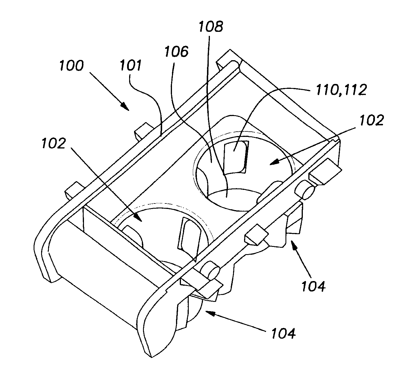
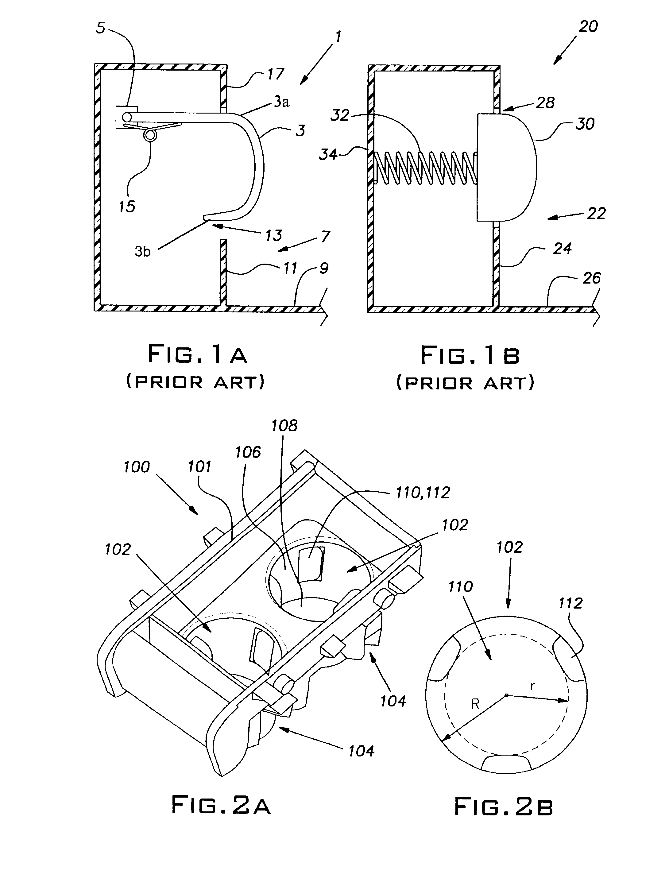
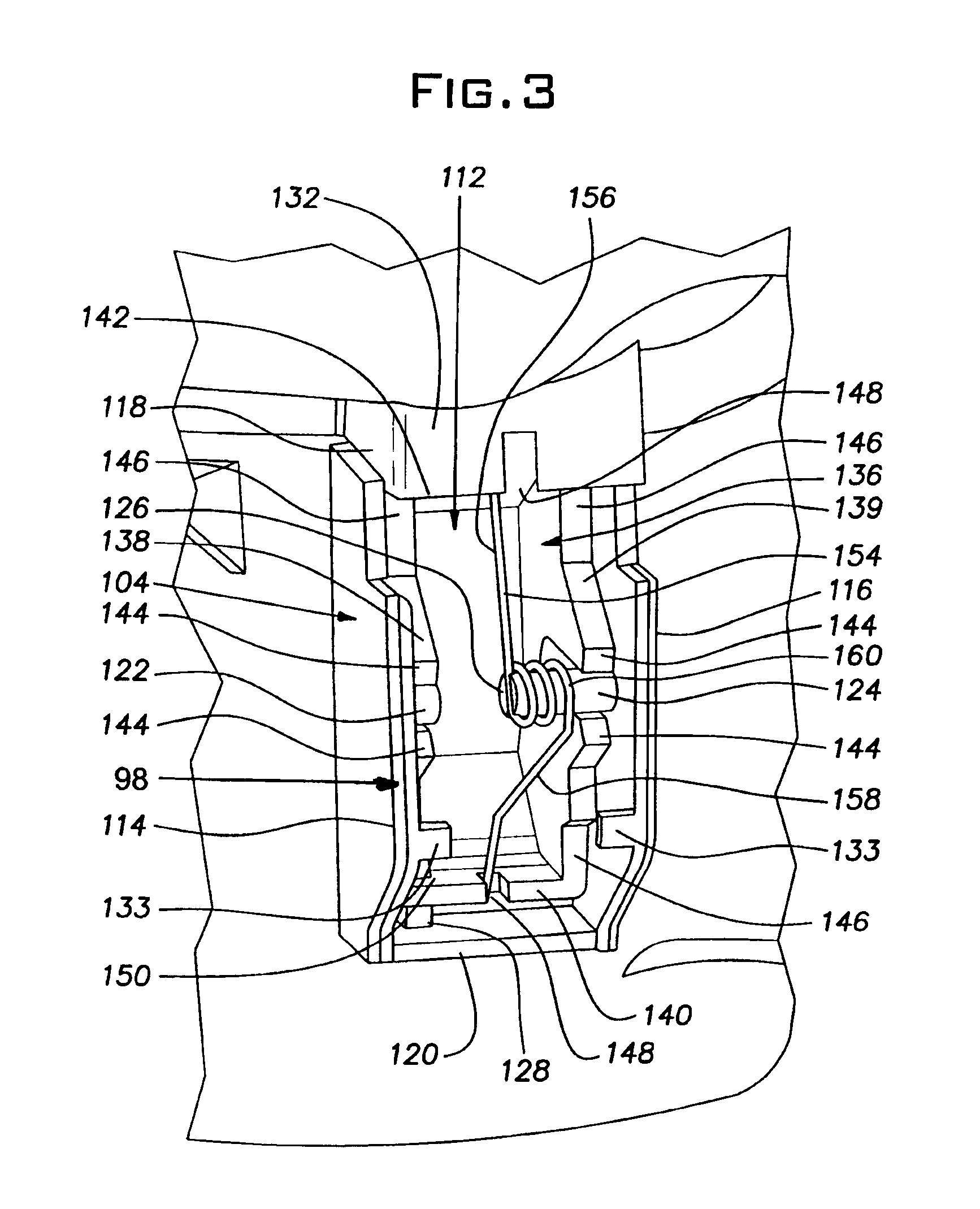
[0026]The present invention seeks to solve the problems associated with conventional cup holder tab assemblies. With reference to FIGS. 2A and 2B, an embodiment of a cup holder with an improved tab structure is shown. A cup holder 100 includes a main body 101 and a plurality of tab assemblies 98, each of the tab assemblies comprising a tab 112 and a biasing member or spring 154.

[0027]The main body 101 has a pair of cylindrical openings 102 formed therein, and supports or receives a plurality of tab assembly supporting structures 104. Each cylindrical opening 102 has a diameter large enough to receive a cup with a relatively large diameter, and a depth sufficient to provide adequate support for tall cups. ...


PUM


Abstract

A cup holder with a securing mechanism for use in a vehicular cup holder for receiving and securing different sized cups. The cup holder includes a cylindrical opening defined by a cylindrical wall and bottom wall, tab openings formed in the cylindrical wall, tabs projecting through the openings, and a biasing device for biasing the tabs. The tabs are attached to the cup holder so as to be movable in a horizontal direction and to be rotatable in a vertical direction about a central pivot point. The tabs are biased so as to project fully into the cylindrical opening and to be in a non-pivoted position.

Description

BACKGROUND OF THE INVENTION[0001]The present invention relates to a cup holder in a vehicle. Conventionally, cup holders are located in a center console for the driver and front seat passenger and somewhere along the back of the front seats or in a rear console or arm rest for passengers in the rear of the vehicle. The cup holders are generally provided by a plastic or rubber cylindrical opening within the interior trim of the vehicle. The cylindrical opening generally has a diameter designed to receive a cup with an average diameter.[0002]A problem with conventional cup holders arises when a cup having a smaller or larger than average diameter is inserted into the cup holder. When a cup has a smaller than average diameter, the cup holder opening is too big for the cup. This leads to the cup not being properly secured within the cup holder, creating a risk of the cup tipping over. When the cup has a diameter larger than the cup holder, the cup won't fit into the opening.[0003]To rem...

Claims


Application Information

Patent Timeline
Patent Type & Authority Patents(United States)
IPC IPC(8): B65D25/00B60R7/00A47B96/06
CPCB60N3/106Y10S224/926
Inventor KEARNEY, CHRISTIANYODA, TADASHI
Owner HONDA MOTOR CO LTD
Why Eureka
Try Eureka