
Battery pack with vertical cells and slide in latch

a vertical cell and battery pack technology, applied in the field of batteries, can solve the problems of difficult to construct compact batteries, difficult to handle such large batteries, and difficult to carry, and achieve the effect of convenient handling

Active Publication Date: 2005-11-15
HILTI AG
View PDF4 Cites 21 Cited by
  • Summary
  • Abstract
  • Description
  • Claims
  • Application Information

AI Technical Summary

Benefits of technology

[0006]The object of the present invention is to provide a battery pack that is structurally compact and easy to handle. In addition, the battery pack must be securely attachable to the cordless electrical appliance.
[0008]The structural height of the inventive system with the at least partially translatory guided actuation means is only minimally greater than the structural height in the known hinged or flexural mechanism. In comparison to the hinged or flexural mechanism, greater movements of the actuation means can be effected in the inventive system such that even heavier battery packs can be adequately secured. The inventive system can be easily operated as a result of the arrangement of the actuation means in the recess of the side wall of the housing. The at least one recess is preferably provided in a flat surface of a respective side wall. The actuation means are, for example, configured as push-buttons that have a large contact surface. As a result of this arrangement, handling of the battery pack is simplified. If, for example, the battery pack is suspensively attached to the electrical appliance using a rocker mechanism, in the battery pack of the invention, then changing between different grip positions, as is the known pivot- and flexure mechanisms, is unnecessary when attaching and detaching the battery pack.
[0009]The at least one actuation means is preferably configured so that it is guided in the opening of the groove over its entire stroke. In this manner, the at least one actuation means will not wedge or jam when it is used. In addition, guide rails for guiding the at least one actuation means can be provided on the floor part or the cover part.
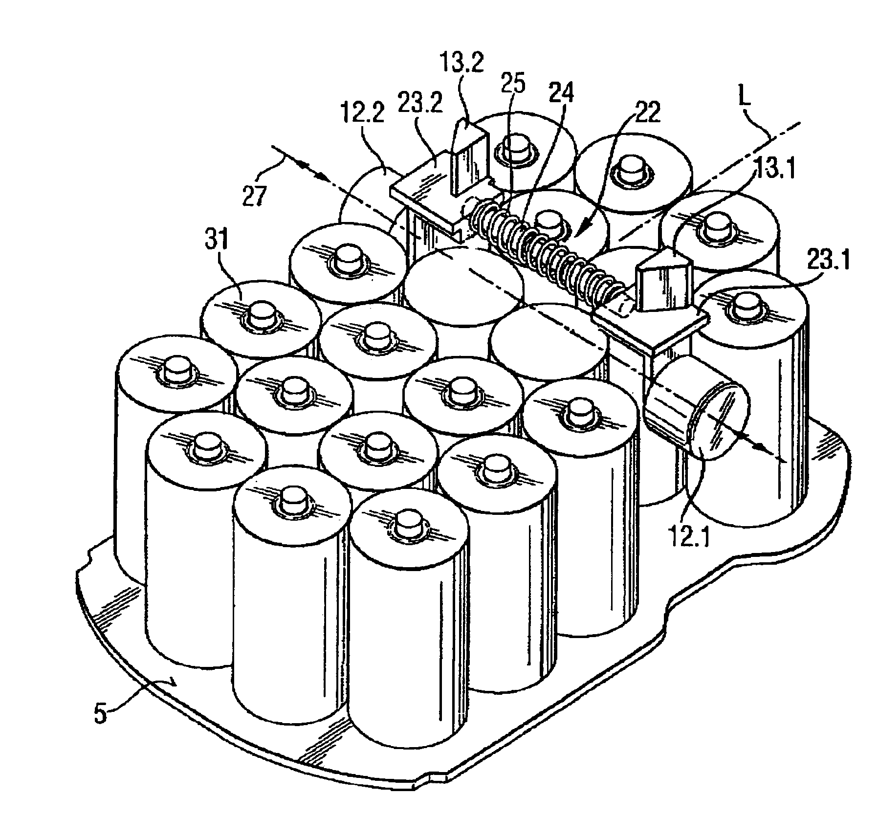
[0011]Preferably, the guide means includes a guide bar. The at least one actuation means is preferably configured as an additional guide means of the at least one actuation means, so that the translatory movement is possible, over the entire working life of the battery pack. The guide rod can, for example, be fabricated out of an elastic, compressible material. When the push-button is actuated there is a compression of the guide bar and the length of the guide bar is shortened. After release of push-button, the guide bar urges against its original length and thus restores the push-button back to its starting position. The guide bar is, for example, passed through the housing and is supported on the side wall situated opposite the side wall having the actuation means or the recess. The guide bar can also be configured such that the guide of the at least one actuation means along its translatory axis occurs only or predominantly via the guide bar.
[0015]Preferably, the latching device comprises two actuation means and the side walls each have a recess. The fitness for purpose and handling of the battery pack, in such an embodiment, is substantially improved. On the one hand, the battery pack is detachably held on the electrical appliance at at least two points and, on the other hand, the battery pack is easier to detach from the electrical appliance. If, for example, the battery pack is stuck on the electrical appliance, by user error or distortion of the housing of the battery pack, the battery pack can in the majority of instances be loosened at at least one actuation means and detached from the electrical appliance using ancillary tools.
[0016]Preferably, the recesses are configured opposite to each other on the side walls. In this embodiment type, the operation of the actuation means is simplified for single-handed operation. The battery pack is, for example, held from below or from the rear with one hand and the actuation means can be operated using two fingers. The risk of the battery pack falling to the floor, at the time of attaching or detaching, is reduced to a minimum.

Problems solved by technology

The drawback in the conventional system is that the battery pack, especially in 12 V electrical voltage systems and higher, is quite heavy.
Handling such large battery packs is awkward.
Furthermore, the battery packs are very sensitive to impact, and thus the well-known snap-in mechanism only conditionally meets the demands of a battery pack over its service life.
The possibility to construct a compact battery pack is limited since the locking tabs pivotable relative to the housing require a certain space for their functionality.

Method used


Image

  • Battery pack with vertical cells and slide in latch
  • Battery pack with vertical cells and slide in latch
  • Battery pack with vertical cells and slide in latch

Examples


Embodiment Construction

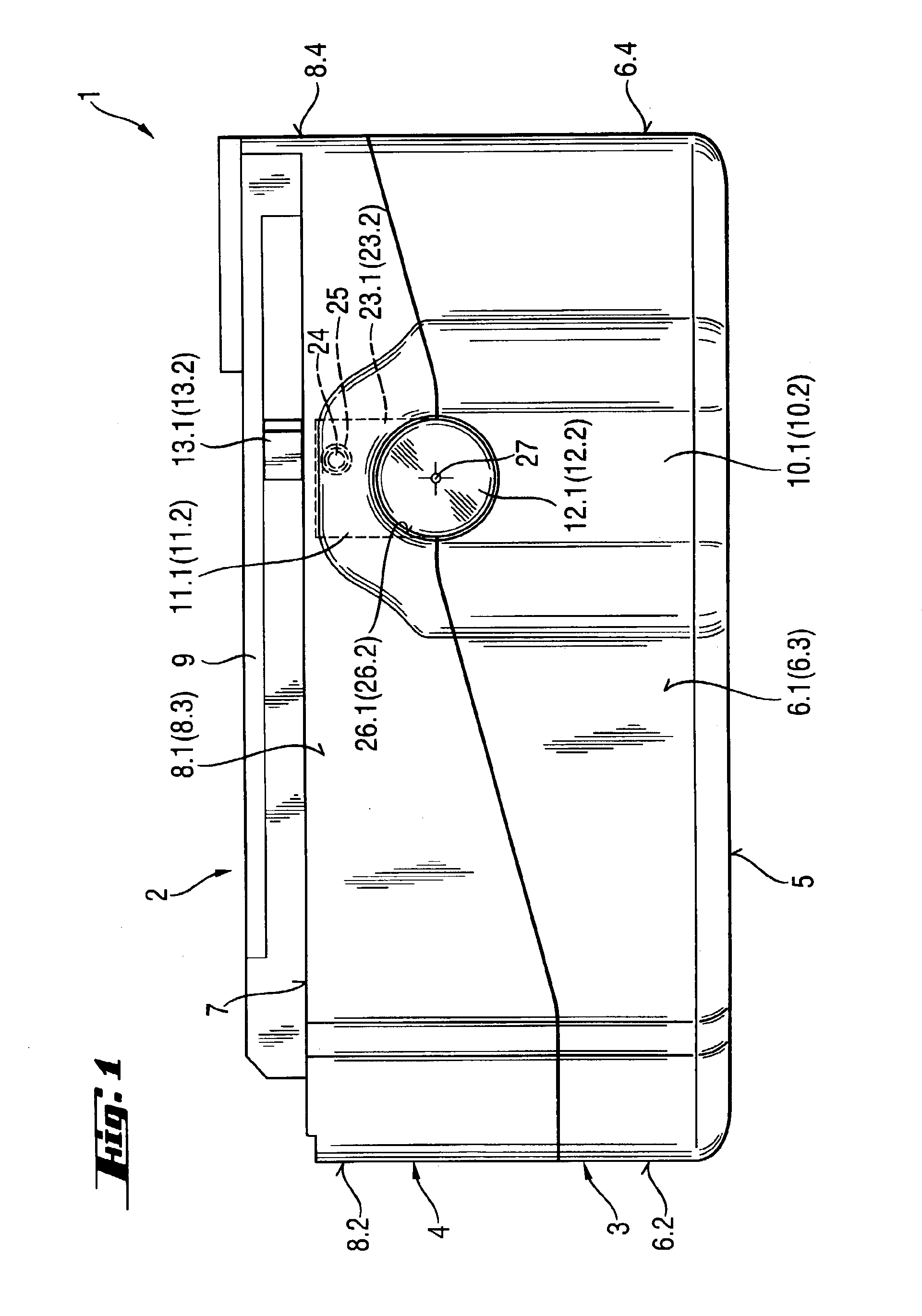
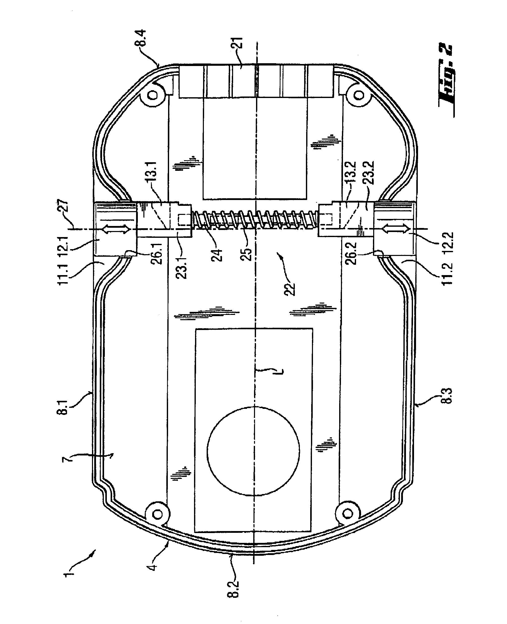
[0022]A side view of a battery pack according to the invention is shown in FIG. 1. The battery pack 1 has a two-part housing 2, which includes a bottom shell 3 and a cover shell 4. The bottom shell 3 has a floor part 5. Side walls 6.1 to 6.4 (the side wall 6.3 is obscured in this representation by the side wall 6.1) are vertically arranged at the edges of the floor part 5. The cover shell 4 has a cover part 7 and side walls 8.1 to 8.4 (the side wall 8.3 is obscured in this representation by side wall 8.1). Guide means 9 are arranged on the cover part 7. The guide means can engage into respective complementary engaging means on the electrical appliance (not shown herein).

[0023]The side walls 6.1 and 6.2 and 8.1 and 8.2 are each provided with a recess 10.1 and 10.2 or 11.1 and 11.2 that in the assembled state of the bottom shell 3 and the cover shell 4 is open towards the floor part 5. Push-buttons 12.1 and 12.2 are disposed in the recesses 11.1 and 11.2 for unlatching the latching de...


PUM


Abstract

A battery pack (1) has a housing (2) with a floor part (5) and side walls (6.1, 6.2, 6.4; 8.1, 8.2, 8.4). The side wall (6.1, 8.1) has a recess (10.1, 11.1) oriented towards the inside of the housing. A plurality of cells arranged vertical to the floor part (5) are arranged in the housing (2). An actuation means (12.1) is provided in the recess (10.1, 11.1) for actuating the latching device and unlatching the detent element (13.1) from the receptacle of the electrical appliance. The actuation means (12.1) is guided on a guide means displaceable relative to the housing (2), and a translatory axis of the actuation means (12.1) is oriented vertical to the side wall (6.1, 8.1) and parallel to the floor part (5).

Description

FIELD OF THE INVENTION[0001]The invention relates to a battery pack with a housing having a floor part and at least two side walls running parallel to each other and perpendicular to the floor part, wherein the housing has at least a recess at one of the side walls oriented towards the inside of the housing, a plurality of cells inside the housing oriented perpendicular to the floor part and a locking mechanism with at least one actuation means for unlocking the locking mechanism arranged in at least one recess.BACKGROUND OF THE INVENTION[0002]Battery packs can be used in cordless electrical appliances with chargeable storage cells for skilled workers, professionals and widely used routine use. For example, nickel-cadmium or nickel-metal hybrids battery cells are used as the storage cells, wherein several such cells are combined to form a battery pack. In the discharged state of the battery pack, the cells can be recharged using a charger device. Embodiments are well-known, in which...

Claims


Application Information

Patent Timeline
IPC IPC(8): H01M2/10H02J7/00H01M2/02H01MH01M6/42
CPCH01M2/1055H01M2/0217H01M6/42H01M50/103H01M50/213
Inventor SCHADOFFSKY, OLAFONTL, RAINER
Owner HILTI AG
Learn More