System and method for generating optical return-to-zero signals with differential bi-phase shift and frequency chirp

a technology of bi-phase shift and frequency chirp, applied in the field of telecommunication techniques, can solve the problems of high cost and complexness of the conventional system 100/b> for generating csrz signals, and achieve the effects of reducing the complexity of the transmitter, improving the reliability of the transmitter, and reducing the cost of the transmitter

Active Publication Date: 2010-09-07
FUTUREWEI TECH INC
View PDF17 Cites 8 Cited by
  • Summary
  • Abstract
  • Description
  • Claims
  • Application Information

AI Technical Summary

Benefits of technology

[0023]Certain embodiments of the present invention can generate an optical return-to-zero signal with differential bi-phase shift and frequency chirp. For example, the differential bi-phase shift can improve dispersion tolerance of the optical signal. In one embodiment, every return-to-zero pulse that represents a logic high level has a 180-degree phase shift from its nearest return-to-zero pulse that also represent the logic high level. So when the signal pulses are broadened by fiber dispersion, interference between the nearest return-to-zero pulses is destructive. In another example, the frequency chirp can increases signal resistance to nonlinear distortion and enhance signal transmission properties. In one embodiment, with negative frequency chirp, the optical return-to-zero signal would be compressed to shorter pulses after transmitting certain distance in positive dispersion fibers.
[0025]Certain embodiments of the present invention provide systems and methods that use only one Mach-Zehnder (MZ) data modulator to generate the differential RZ (DRZ) signals with frequency chirp. Some embodiments of the present invention can significantly lower the cost of a transmitter for optical DRZ signals with frequency chirp. Certain embodiments of the present invention can significantly reduce the complexity of a transmitter for optical DRZ signals with frequency chirp. Some embodiments of the present invention can significantly improve reliability of a transmitter for optical DRZ signals with frequency chirp. Certain embodiments of the present invention can significantly improve performance of a fiber optical transport system. For example, the fiber optical transport system is used for transmission at a high data rate, such as a rate higher than 10 Gbps.

Problems solved by technology

As shown in FIG. 1, the conventional system 100 for generating CSRZ signals often is complex and expensive.

Method used


Image

  • System and method for generating optical return-to-zero signals with differential bi-phase shift and frequency chirp
  • System and method for generating optical return-to-zero signals with differential bi-phase shift and frequency chirp
  • System and method for generating optical return-to-zero signals with differential bi-phase shift and frequency chirp

Examples


Embodiment Construction

[0040]The present invention relates in general to telecommunication techniques. More particularly, the invention provides a system and method for generating optical return-to-zero signals with differential bi-phase shift and frequency chirp. Merely by way of example, the invention is described as it applies to optical networks, but it should be recognized that the invention has a broader range of applicability.

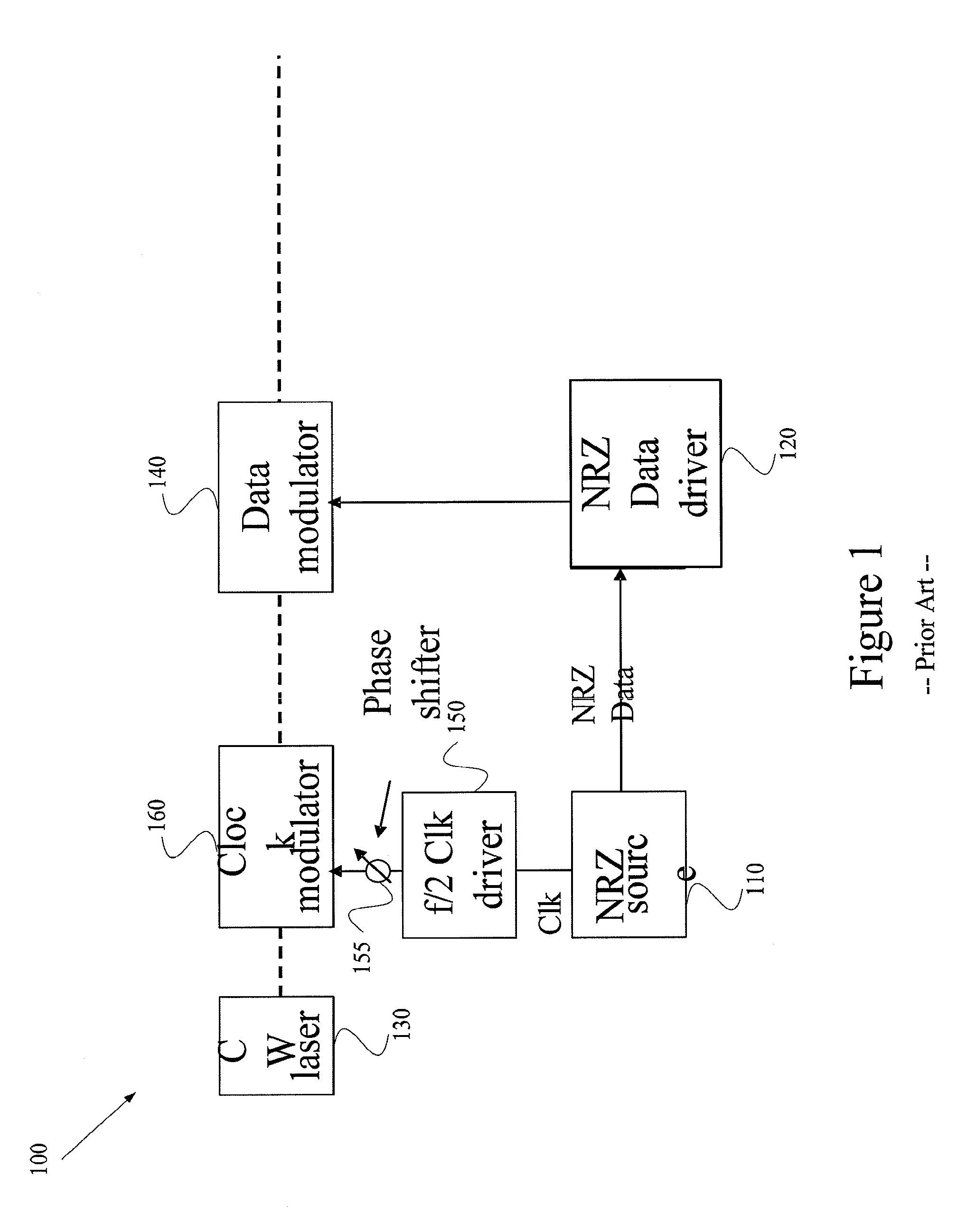
[0041]As shown in FIG. 1, the system 100 uses two EO modulators and related driving circuits to perform optical double modulations. For example, a first MZ modulator is used for clock-pulse modulations, and a second MZ modulator is used for data modulations. The clock pulses received by the first MZ modulator are often generated by nonstandard parts, which can be very expensive. Additionally, the optical data modulations and the optical clock modulations usually need to overlap temporally, so the clock pulses should be kept substantially at the center of the bit slot. But keep...


PUM


Abstract

A system and method for generating an optical return-to-zero signal. The system includes an electro-optical conversion system. The electro-optical conversion system is configured to receive an input electrical non-return-to-zero signal, process information associated with the input electrical non-return-to-zero signal, and generate an output optical return-to-zero signal based on at least information associated with the input electrical non-return-to-zero signal. The output optical return-to-zero signal is an optical differential return-to-zero signal, and the optical differential return-to-zero signal is associated with a frequency chirp.

Description

CROSS-REFERENCES TO RELATED APPLICATIONS[0001]This application claims priority to U.S. Provisional Application No. 60 / 710,668, filed Aug. 22, 2005, which is incorporated by reference herein.[0002]The following three commonly-owned co-pending applications are hereby incorporated by reference in their entirety for all purposes:[0003]1. U.S. patent application Ser. No. 11 / 336,658, in the name of Yu Sheng Bai, titled, “System and Method for Generating Optical Return-to-Zero Signals with Alternating Bi-Phase Shift,”, filed Jan. 20, 2006;[0004]2. U.S. patent application Ser. No. 11 / 336,619, in the name of Yu Sheng Bai, titled, “System and Method for Generating Optical Return-to-Zero Signals with Alternating Bi-Phase Shift and Frequency Chirp,”, filed Jan. 20, 2006; and[0005]3. U.S. patent application Ser. No. 11 / 344,958, in the name of Yu Sheng Bai, titled, “System and Method for Generating Optical Return-to-Zero Signals with Differential Bi-Phase Shift,”, filed Jan. 31, 2006.STATEMENT AS...

Claims


Application Information

Patent Timeline
Patent Type & Authority Patents(United States)
IPC IPC(8): H04B10/04
CPCH04B10/505H04B10/5051H04B10/5055H04B10/5162H04B10/5561H04L25/4904
Inventor BAI, YU SHENG
Owner FUTUREWEI TECH INC
Why Eureka
Try Eureka