Cold crucible induction furnace

a technology of cold crucible and furnace, which is applied in the direction of furnaces, charge manipulation, lighting and heating apparatus, etc., can solve the problems of limiting the range of metal load capacity, wall-base interface interference with flux transfer to load, and major losses in process heat generated in the wall and base, etc., to enhance coupling and enhance the effect of magnetic coupling

Active Publication Date: 2010-09-14
CONSARC
View PDF8 Cites 4 Cited by
  • Summary
  • Abstract
  • Description
  • Claims
  • Application Information

AI Technical Summary

Benefits of technology

[0007]In another aspect, the invention is a cold crucible furnace having a crucible volume formed from an at least partially slotted furnace wall and base. A plurality of protrusions separate the slotted furnace wall from the base. A gap may be provided between each of the protrusions and the base. At least one induction coil is disposed around the furnace wall. A power source provides AC current to the induction coil, which generates a magnetic field that couples with an electrically conductive material placed in the crucible volume. The protrusions between the furnace wall and base enhance the magnetic coupling between the field and the material particularly around the region of the base. Slots may also be provided in the protrusions and / or the outer perimeter of the base to further enhance the coupling between the field and the material.

Problems solved by technology

Heat generated in the wall and base represent the major losses in the process.
A disadvantage of the conventional cold crucible 100 in FIG. 1 is that the wall-base interface interferes with flux transfer to the load in the vicinity of the interface.
This decrease in flux effectively limits the range of metal load capacity that the furnace can efficaciously operate within.
Below 60 percent capacity, the quantity of supplied energy and / or process time increases to the point that the melting process becomes extremely inefficient.
Consequently, the user of the furnace is severely limited in actual capacity operating range relative to the total capacity of the crucible.

Method used


Image

  • Cold crucible induction furnace
  • Cold crucible induction furnace
  • Cold crucible induction furnace

Examples


Embodiment Construction

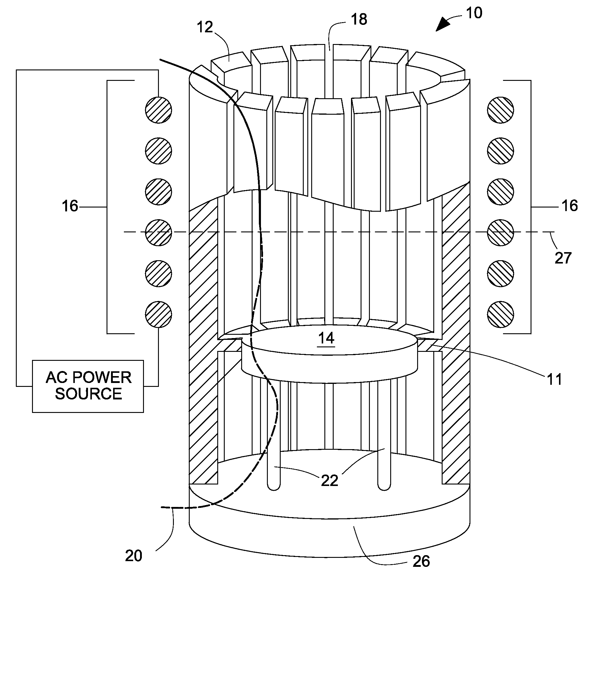
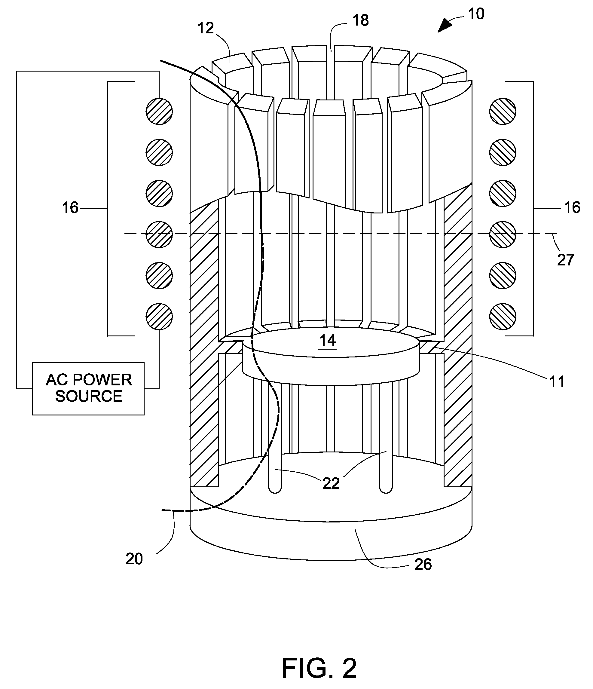
[0021]There is shown in FIG. 2 and FIG. 3, one example of a cold crucible induction furnace 10 of the present invention. Furnace 10 includes wall 12 that has a plurality of protrusions 11 into the volume of the crucible adjacent to base 14. The protrusions extend around the wall's inner perimeter and may be formed either as an integral part of the wall or fitted within wall 12. Annular protrusions 11 are generally composed of the same material as wall 12. While the annular protrusions are shown with a substantially rectangular cross section, other cross sectional shapes, such as but not limited to, semicircular and semielliptical, or sloped, are within the scope of the invention. Further, although all protrusions 11 for this particular example of the invention are all of the same size and shape, protrusions of varying sizes and shapes may be used. Slots 18 are substantially continuous vertical slots through wall 12 and protrusions 11. The slots may be terminated in the wall at a dis...


PUM

PropertyMeasurementUnit
electrically conductiveaaaaaaaaaa
volumeaaaaaaaaaa
heightaaaaaaaaaa

Abstract

A cold crucible induction furnace has a slotted-wall with a slotted inner annular protrusion that is disposed around the base of the crucible's melting chamber. The protrusions may be separated from the base by a gap that can be filled with an electrical insulating material. Slots may also be provided in the protrusions and / or the outer perimeter of the base.

Description

CROSS REFERENCE TO RELATED APPLICATIONS[0001]This application claims the benefit of U.S. Provisional Application No. 60 / 537,113 filed Jan. 16, 2004, hereby incorporated herein by reference in its entirety.FIELD OF THE INVENTION[0002]The present invention is in the technical field of melting electrically conductive materials by magnetic induction with a cold crucible induction furnace.BACKGROUND OF THE INVENTION[0003]A cold crucible induction furnace is used to melt electrically conductive materials placed within the crucible by applying a magnetic field to the material. A common application of such furnace is the melting of a reactive metal or alloy, such as a titanium-based composition, in a controlled atmosphere or vacuum. FIG. 1 illustrates the principle features of a conventional cold crucible furnace. Referring to the figure, crucible 100 includes slotted wall 112. The interior of wall 112 is generally cylindrical. The upper portion of the wall may be somewhat conical in shape ...

Claims


Application Information

Patent Timeline
Patent Type & Authority Patents(United States)
IPC IPC(8): H05B6/22H05B6/02H05B6/24
CPCF27B14/063F27B14/14H05B6/24
Inventor KEOUGH, GRAHAM A.
Owner CONSARC
Why Eureka
Try Eureka