Measuring arrangement for flow measurement in a channel

Active Publication Date: 2010-09-21
TESTO AG
View PDF9 Cites 11 Cited by
  • Summary
  • Abstract
  • Description
  • Claims
  • Application Information

AI Technical Summary

Benefits of technology

[0008]Unlike the related art, in the system described herein the problem of the influence of the flow profile over the cross section of the flow channel on the measurement result for the average flow velocity is solved not by adapting and calibrating a Pitot tube specif

Problems solved by technology

Such a measurement of the average flow velocity is too inaccurate, however, and the particular flow profile must be included in the measurement result.
This is only a minor problem with permanently installed Pi

Method used


Image

  • Measuring arrangement for flow measurement in a channel
  • Measuring arrangement for flow measurement in a channel
  • Measuring arrangement for flow measurement in a channel

Examples


Embodiment Construction

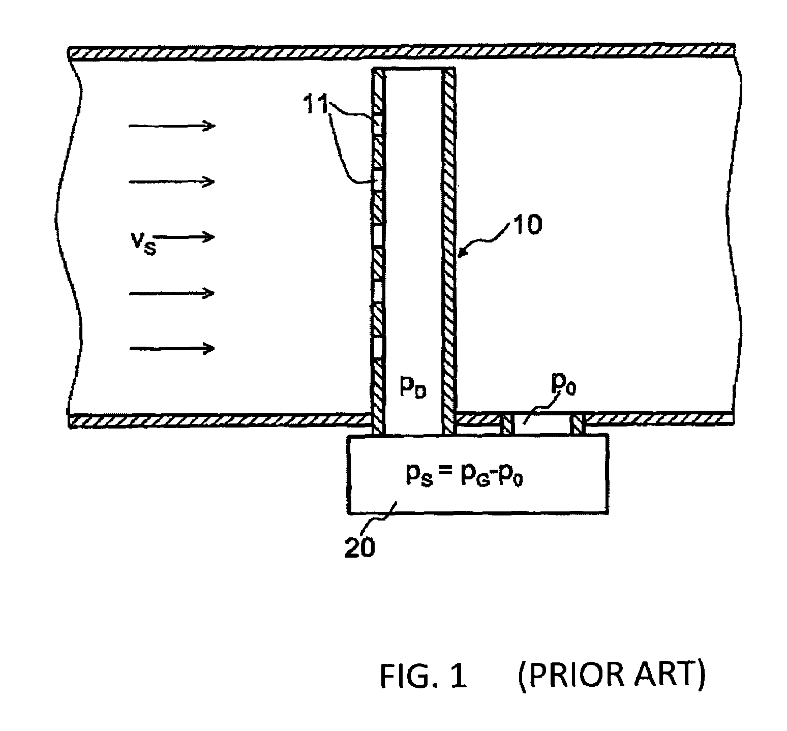
[0026]The same reference numbers in the figures denote the same parts.

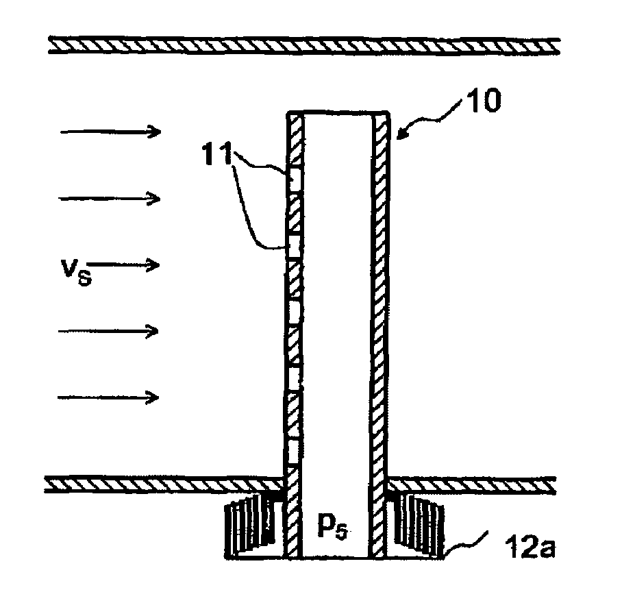
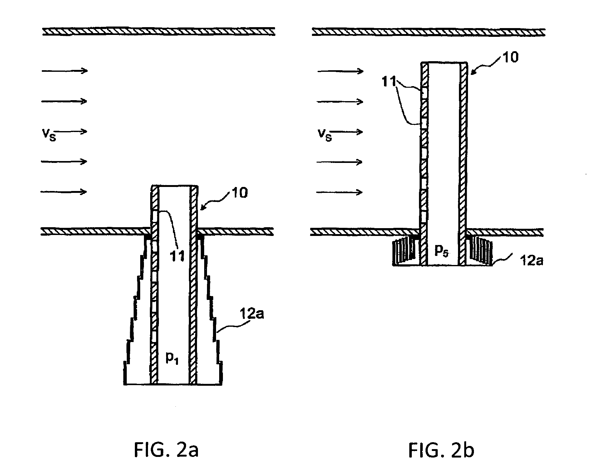
[0027]FIGS. 2a and 2b show a part of the measuring arrangement according to an embodiment of the system described herein, namely a probe tube 10 having openings 11 positioned along a line parallel to the axis of symmetry on the side facing the flow and having a telescoping tube 12a which is pulled over the probe tube and which is suitable for covering one or more of the successive openings or none at all, depending on the set position and length. Probe tube 11 may be inserted into the channel to different distances, depending on how the length of telescoping tube 12a has been set. FIG. 2a shows the telescoping tube in an extended position, in which all the openings except one in the probe tube have been covered by the telescoping tube. Only a single opening is in the flow channel. Thus, now the one remaining opening in the channel contributes toward the formation of total pressure p1 in the interior of the probe t...


PUM


Abstract

A measuring arrangement for determining flow speeds in a flow channel includes a probe tube which is introduced via a first opening into the flow channel. The probe tube is exposed to a flow with a flow speed, the side of the probe tube facing the flow comprising a plurality of openings which are interconnected inside the probe tube such that a total pressure dependent on the flow speed prevails inside the probe tube. The measuring arrangement also comprises a static pressure opening in the flow channel, and a differential pressure sensor that determines the differential pressure between the total pressure inside the probe and the static pressure in the flow channel. The probe tube may be partially surrounded by a shield which is mobile and/or length-adjustable and that, according to its position and/or length along the probe tube, may close one, several or none of the openings.

Description

TECHNICAL FIELD[0001]This application relates to an arrangement for measuring flow velocities and volume flows in a flow channel with the help of a Pitot tube.BACKGROUND OF THE INVENTION[0002]Pitot tubes, also known as dynamic pressure gauges, are widely used sensors in flow meter technology for determining flow velocities. A special form of a Pitot tube is the Prandtl tube, for example, which is used for speed measurement in aviation. However, dynamic pressure gauges are used in ventilation technology in measuring flow velocities, volume flows, or mass flows in ventilation ducts because they are characterized by the possibility of simple assembly and by a low pressure drop in the installed state.[0003]A known design of such dynamic pressure gauges is illustrated in FIG. 1, for example. A probe tube 10 is inserted through an opening into the interior of a flow channel 1. Openings 11 are provided along an axis of probe tube 10 on the side of probe tube 10 facing the flow, so that a t...

Claims


Application Information

Patent Timeline
IPC IPC(8): G01F1/46
CPCG01F1/46
Inventor ROMBACH, MARTINHUG, UDOSTREICHER, MANFREDHALL, JURGEN
Owner TESTO AG
Why Eureka
Try Eureka