
Top mounting fuel injector clip

a fuel injector and clip technology, applied in the direction of liquid fuel feeders, machines/engines, mechanical equipment, etc., can solve the problems that the connection of the hanging injector employed by the mpfis cannot withstand the operating pressure of the di system, and achieve the effect of convenient assembly and disassembly, convenient correct alignment of the injector, and simple and secure keying

Inactive Publication Date: 2010-09-21
DELPHI TECH INC
View PDF14 Cites 12 Cited by
  • Summary
  • Abstract
  • Description
  • Claims
  • Application Information

AI Technical Summary

Benefits of technology

The invention is a fuel injector coupling that allows for a secure and keyed connection between a fuel injector and a fuel rail. The coupling includes a retainer clip and a collar that work together to withstand high fuel pressure. The retainer clip is U-shaped to capture the end face of the fuel rail socket and includes windows to secure the injector in place. The collar has mating features with the clip and the fuel rail socket to ensure correct alignment of the injector. The retainer clip is easy to assemble and disassemble. Overall, the coupling provides a centralized load path and ensures a reliable and durable connection between the fuel injector and fuel rail.

Problems solved by technology

However, such a rigid connection has a drawback in that the metal-to-metal contact of the rigid connection provides a direct path for transmitting injector noise.
However, while such a coupling solves the noise transmission problem of a rigid connection, the hanging injector connection employed by MPFIs cannot withstand the operating pressures of a DI system.

Method used


Image

  • Top mounting fuel injector clip
  • Top mounting fuel injector clip
  • Top mounting fuel injector clip

Examples


Embodiment Construction

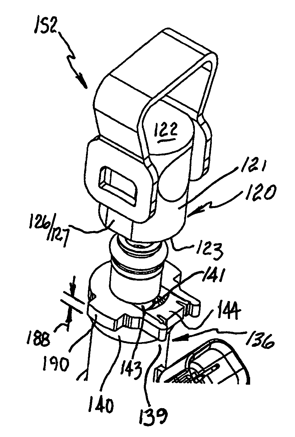
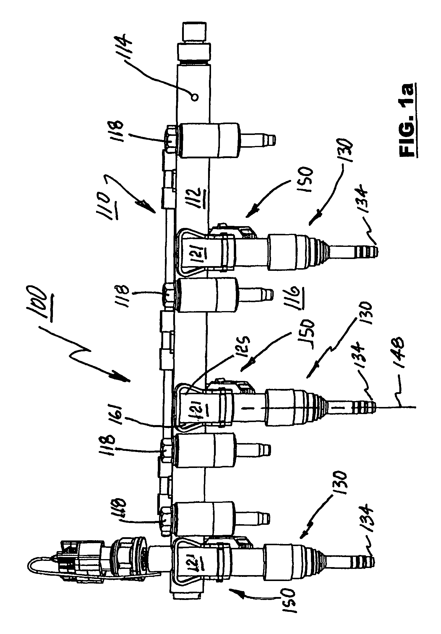
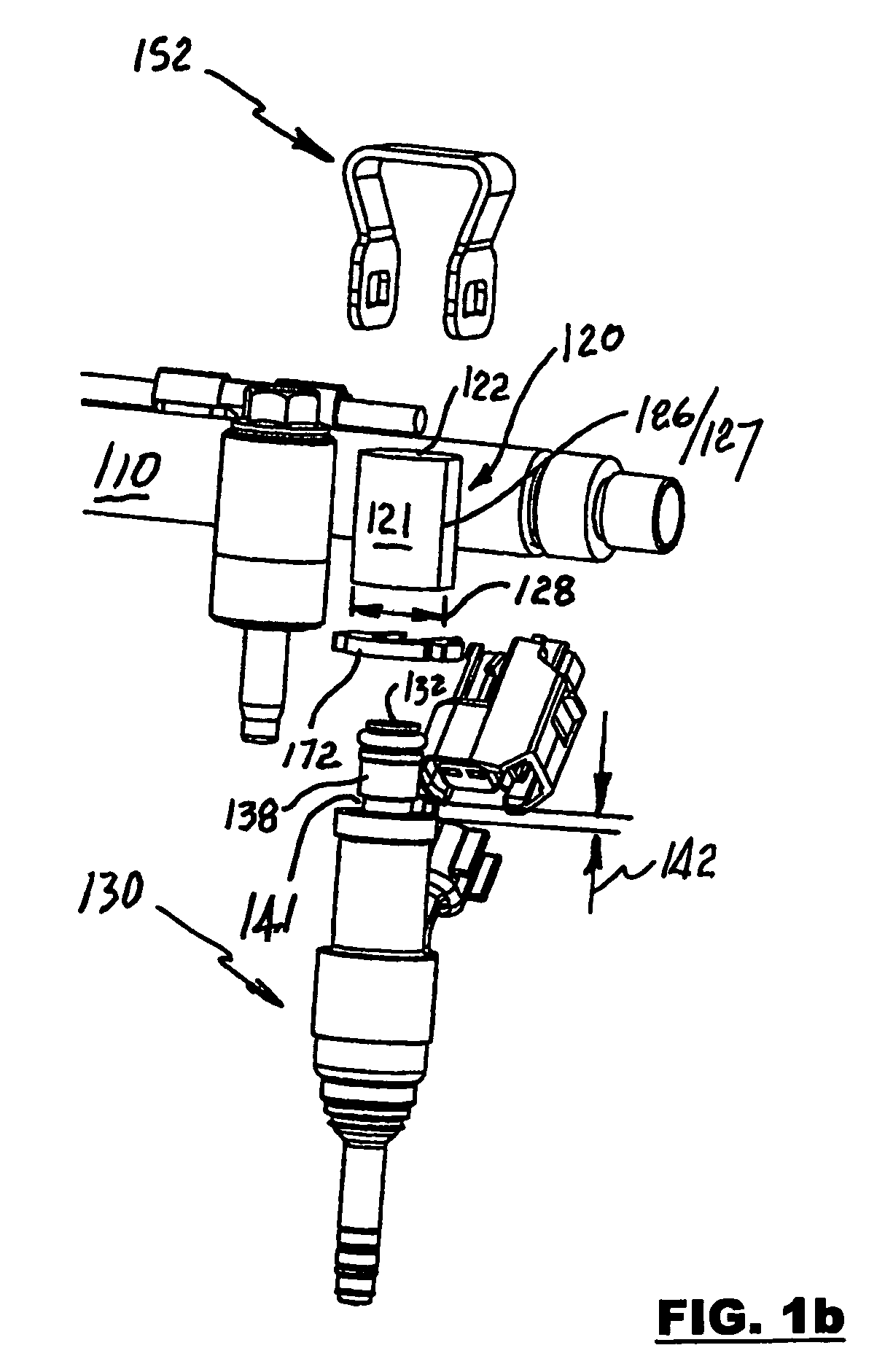
[0017]Referring to FIGS. 1a, 1b, 2a and 2b, an injector fuel system 100, in accordance with the invention, includes a fuel rail assembly 110, at least one fuel injector 130 and, for each fuel injector, a coupling 150. Fuel rail assembly 110 includes a fuel distribution conduit 112 that may be, for example, an elongated tube as shown in FIG. 1 or may be a non-round conduit. At least one injector socket 120 is assembled to conduit 112 to be in fluid communication with the interior of conduit 112 via an opening 114, shown in a right-most position on the fuel rail in FIG. 1 before socket 120 is attached to conduit 112. Fuel rail assembly 110 is connected to a typical fuel supply system (not shown). Fuel rail assembly 110 is secured to cylinder head 116 by, for example, bolts 118 such that, through coupling 150, each fuel injector 130 is precisely aligned with its associated cylinder / combustion chamber (not shown).

[0018]Injector socket 120 may include a cylindrical body 121 that is close...


PUM


Abstract

A coupling for suspending a fuel injector from a fuel rail assembly of an internal combustion engine includes a collar that mates with the fuel injector and a retainer clip that engages with the collar thereby mechanically connecting the fuel injector to the fuel rail assembly. The retainer clip includes windows to enable even load distribution upon the socket flange when assembled. Features are integrated in the collar to facilitate correct alignment of the injector relative to the fuel rail. Paired together, the retainer clip and the collar enable a secure, and a keyed fuel injector-to-fuel rail connection that is able to withstand high pressure separating loads.

Description

TECHNICAL FIELD[0001]The present invention relates to fuel injection systems of internal combustion engines; more particularly to fuel rail assemblies for supplying pressurized fuel to fuel injectors for direct injection into engine cylinders; and most particularly, to an apparatus and method for coupling a fuel injector to a fuel rail for direct injection.BACKGROUND OF THE INVENTION[0002]Fuel rail assemblies for supplying fuel to fuel injectors of internal combustion engines are well known. A fuel rail assembly, also referred to herein simply as a fuel rail, is essentially an elongated tubular fuel manifold connected at an inlet end to a fuel supply system and having a plurality of ports for mating in any of various arrangements with a plurality of fuel injectors to be supplied. Typically, a fuel rail assembly includes a plurality of fuel injector sockets in communication with a manifold supply tube, the injectors being inserted into the sockets.[0003]Fuel injectors may be divided ...

Claims


Application Information

Patent Timeline
Patent Type & Authority Patents(United States)
IPC IPC(8): F02M61/14F02M61/18
CPCF02M55/025F02M61/14F02M63/0275F02M69/465
Inventor NOTARO, CODY C.SMITH, CRAIG L.BRAUN, CHARLES W.URCKFITZ, JASON
Owner DELPHI TECH INC
Learn More