
Instrument for manipulating an implant

a technology for manipulating instruments and implants, applied in the field of manipulating instruments, can solve the problems of inability to provide attachment features, severely limited capacity to accommodate additional attachment features, and difficult to correct the alignment of instruments, etc., and achieve the effect of convenient correct alignment of instruments

Active Publication Date: 2017-10-10
BIOMET UK HEALTHCARE
View PDF17 Cites 0 Cited by
  • Summary
  • Abstract
  • Description
  • Claims
  • Application Information

AI Technical Summary

Benefits of technology

The invention is about a medical instrument that can be used to hold an implant in place during a medical procedure. The instrument has a handle with a rotating wheel and a suction cup for holding the implant. The device also has an alignment guide that helps to align the surgical instrument correctly. The technical effects of this invention include improved stability and precision during procedures, reduced risk of complications, and increased efficiency of the surgical team.

Problems solved by technology

This is particularly the case with acetabular cups, which do not otherwise lend themselves to easy engagement with a gripping or impaction tool.
Attachment to a gripping or impaction tool becomes more problematic when considering single body, or so called monobloc acetabular cups.
In such a component, the capacity to accommodate additional attachment features is severely limited.
The internal bearing surface must remain free of any surface discontinuities or other aberrations and thus is not available for the provision of attachment features.
Even temporary attachment mechanisms have proven extremely difficult to implement.
Similar issues are also encountered in the assembly of a multiple body acetabular cup.
An additional issue that must be considered within the context of implant manipulation is the release of the implant from the relevant tool once the implant is in position.
Such direct contact is undesirable and carries risks of additional accidental contact with the implant and consequent damage to the bearing surface.

Method used


Image

  • Instrument for manipulating an implant
  • Instrument for manipulating an implant
  • Instrument for manipulating an implant

Examples


Embodiment Construction

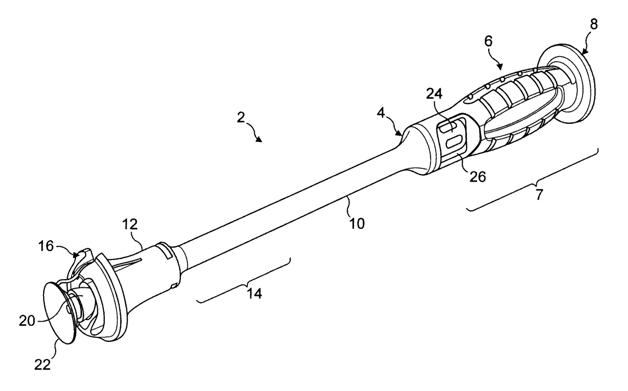
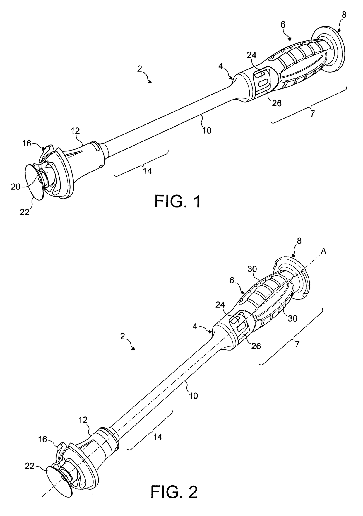
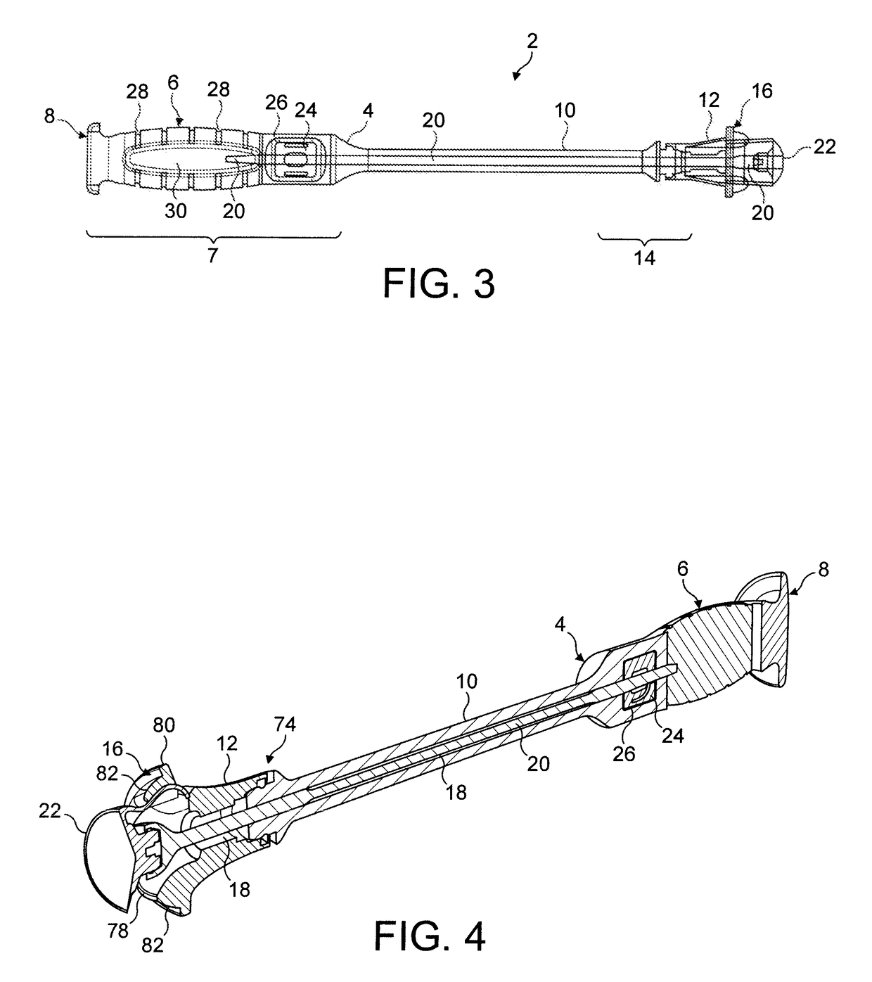
[0079]With reference to FIGS. 1 to 6, an instrument 2 for manipulating an implant comprises a handle 4 having a gripping surface 6 at a proximal end 7 thereof and an impaction surface 8 immediately adjacent the gripping surface 6 and at the extreme proximal end of the instrument 2. The impaction surface 8 extends substantially perpendicular to a longitudinal axis A of the instrument 2 and is operable to receive blows from an impaction device such as a hammer. An elongate main body 10 extends from the gripping surface 6 of the handle along the axis A in a distal direction. An impaction plate 12 is removably mounted on a distal end 14 of the handle. The impaction plate 12 is securely mounted in fixed relation to the handle 4 and comprises an annular impaction surface 16.

[0080]The main body 10 of the handle 4 and the impaction plate 12 are substantially hollow, and when assembled together define a longitudinal bore 18 extending therethrough. Received within the bore 18 is an actuation ...


PUM


Abstract

An instrument (2) for manipulating an implant is disclosed, the instrument (2) comprising an attachment element (22), which is operable to engage an implant, an actuation rod (20), a distal end (34) of which is connected to the attachment element (22) and a handle (4) having a gripping surface (6). At least a proximal end (32) of the actuation rod (20) is moveably received within the handle (4). The instrument further comprises a drive mechanism (42), mounted on the handle (4) and operable to drive relative movement between the actuation rod (20) and the handle (4). Also disclosed is an instrument (2) for manipulating an implant, the instrument (2) comprising a handle (4), a suction cup (22) operable to engage a surface of an implant and moveably mounted with respect to the handle (4), and a release cord (104), fixedly connected between an edge (88) of the suction cup (22) and the handle (4). A method of releasing an implant from an instrument (2) to which it is attached is also disclosed. The method comprises displacing the suction cup (22) and associated implant with respect to the handle (4) until the release cord (104) causes peel back of the edge (88) of the suction cup (22).

Description

CROSS-REFERENCE TO RELATED APPLICATIONS[0001]This application is a 371 U. S. National Stage of International Application No. PCT / GB2011 / 052376, filed on Dec. 1, 2011 and published in English as WO 2012 / 073033 A1 on Jun. 7, 2012. This application claims priority to British Patent Application No. 1020425.3, filed on Dec. 2, 2010. The disclosures of the above applications are incorporated herein by reference in their entirety.[0002]The present invention relates to an instrument for manipulating an implant, and particularly, but not exclusively, relates to an instrument for handling and impaction of a joint prosthesis component, such as an acetabular cup.BACKGROUND[0003]During a joint replacement procedure, it is necessary to manipulate prosthesis components into their required positions with respect to patient anatomy. In the case for example of a hip replacement prosthesis, it is necessary to manoeuvre an acetabular cup into a prepared patient acetabulum, and it may also be necessary ...

Claims


Application Information

Patent Timeline
Patent Type & Authority Patents(United States)
IPC IPC(8): A61B17/00A61F2/46A61F2/34
CPCA61B17/00A61F2/4609A61F2/4637A61F2002/4685A61F2/34A61F2002/4681A61F2/4603
Inventor SLADE, JONATHAN JAMESELLIOTT, MARC DAVID
Owner BIOMET UK HEALTHCARE
Learn More