Apparatus and process for regenerating catalyst

a technology of apparatus and catalyst, applied in the field of apparatus and process for regenerating catalyst, can solve the problems of reducing separation efficiency, and achieve the effects of increasing throughput, reducing separation efficiency, and increasing disengager discharge velocity

Active Publication Date: 2010-09-21
UOP LLC
View PDF18 Cites 22 Cited by
  • Summary
  • Abstract
  • Description
  • Claims
  • Application Information

AI Technical Summary

Benefits of technology

[0009]We have found that as regenerator vessels are getting larger and throughput is increased in the catalyst regenerator, the flue gas exiting the riser through a tee disengager into a disengaging chamber is sweeping catalyst that has collected in a bed in the bottom of the chamber. The swept up catalyst is becoming re-entrained in the ascending flue gas. This phenomenon is due to increased disengager discharge velocities from the riser and greater radial gas velocities over the catalyst fluidized bed. As a result, catalyst that had already been separated from flue gas has to be re-separated in the cyclone separators in the vessel which is overloading the cyclone separators and reducing their separation efficiency. We have discovered that a curved disengager with a relatively large discharge opening and a vertical baffle limits radial flow and directs the discharged catalyst downwardly to the bed. The greatly reduced radial velocity of the flue gas across the catalyst bed minimizes the tendency of the flue gas to sweep catalyst in the bed into re-entrainment.

Problems solved by technology

As a result, catalyst that had already been separated from flue gas has to be re-separated in the cyclone separators in the vessel which is overloading the cyclone separators and reducing their separation efficiency.

Method used


Image

  • Apparatus and process for regenerating catalyst
  • Apparatus and process for regenerating catalyst
  • Apparatus and process for regenerating catalyst

Examples


Embodiment Construction

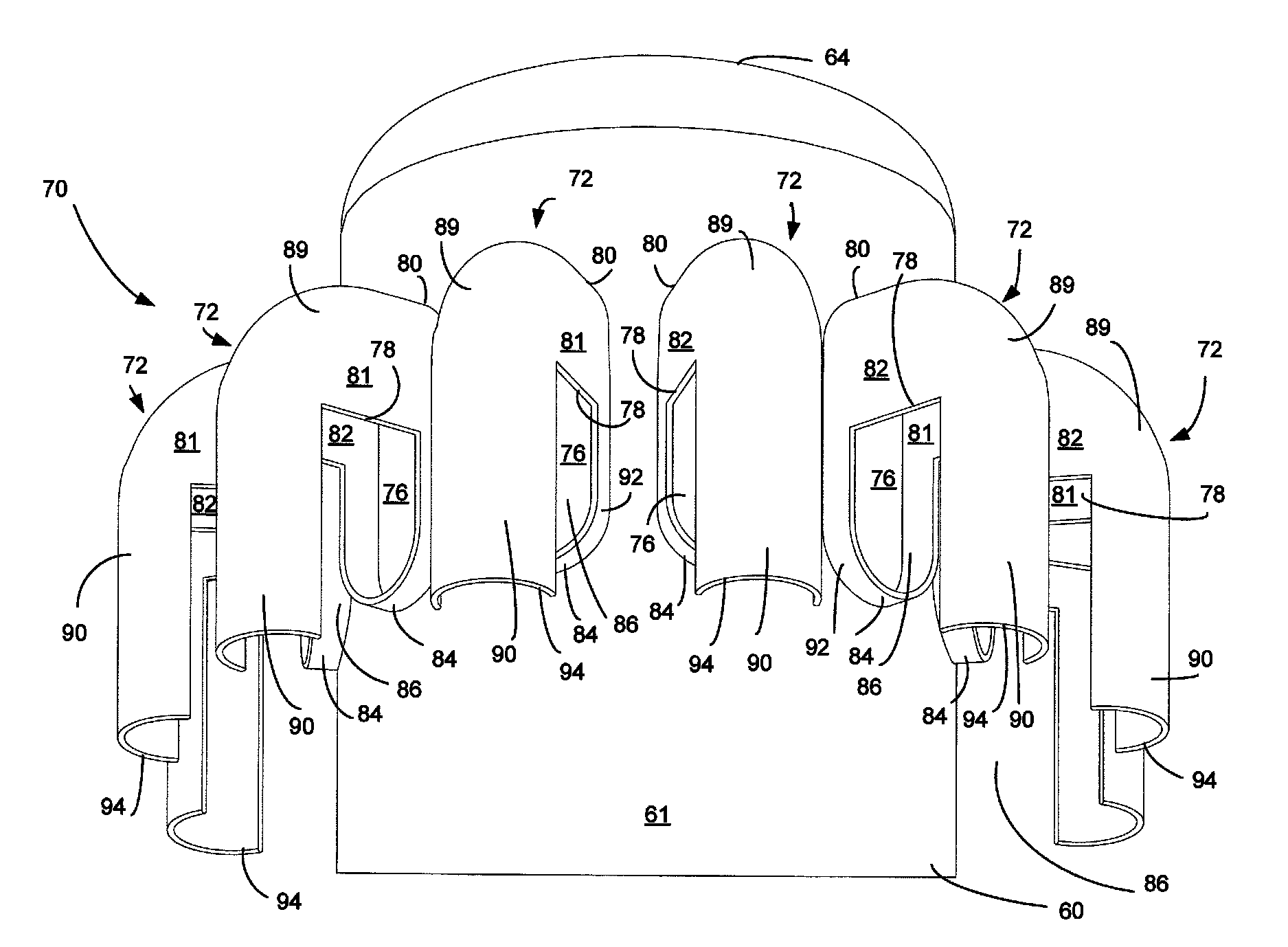
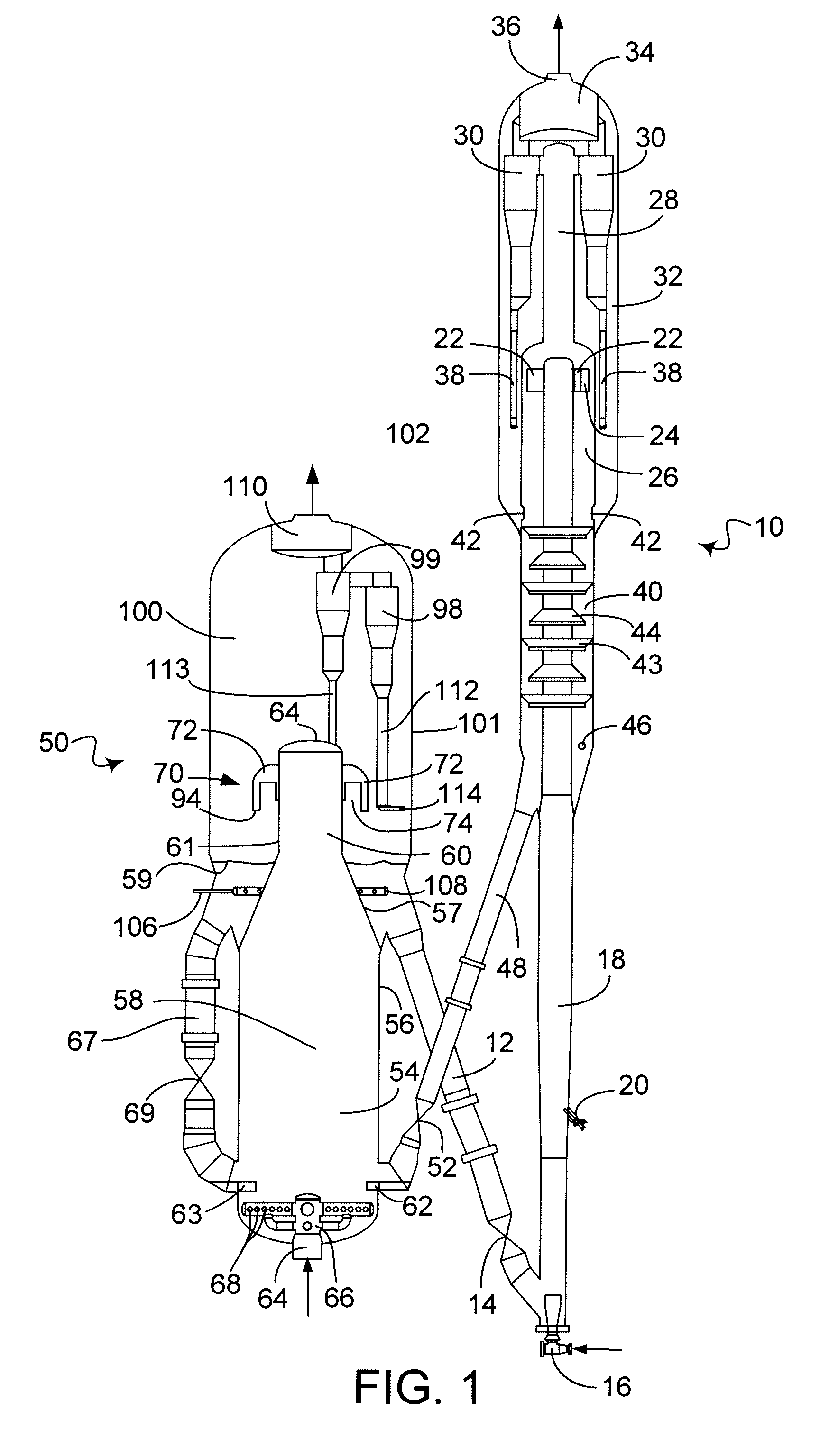
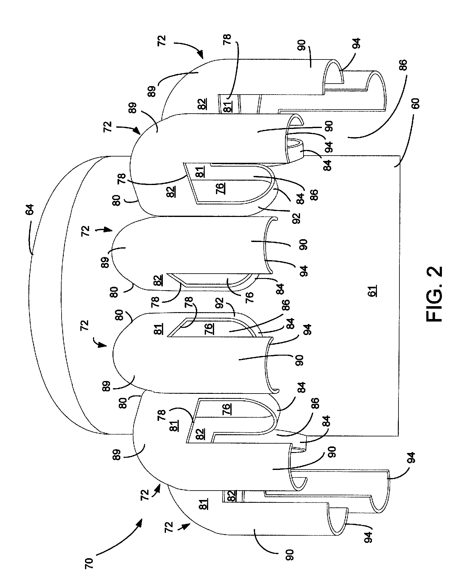
[0017]The process and apparatus of the present invention may be embodied in an FCC unit. FIG. 1 shows an FCC unit that includes a reactor vessel 10 and a regenerator vessel 50. A regenerator standpipe 12 transfers catalyst from the regenerator vessel 50 at a rate regulated by a slide valve 14 to the reactor vessel 10. A fluidization medium such as steam from a nozzle 16 transports catalyst upwardly through a riser 18 at a relatively high density until a plurality of feed injection nozzles 20 (only one is shown) inject feed across the flowing stream of catalyst particles.

[0018]A conventional FCC feedstock or higher boiling hydrocarbon feedstock are suitable feeds. The most common of such conventional feedstocks is a “vacuum gas oil” (VGO), which is typically a hydrocarbon material having a boiling range of from 343 to 552° C. (650 to 1025° F.) prepared by vacuum fractionation of atmospheric residue. Such a fraction is generally low in coke precursors and heavy metal contamination whi...


PUM

PropertyMeasurementUnit
superficial velocityaaaaaaaaaa
superficial gas velocityaaaaaaaaaa

Abstract

Disclosed is an apparatus and process for disengaging regenerated catalyst from flue gas in a catalyst regenerator so as to avoid re-entrainment of catalyst that has settled into a bed in the catalyst regenerator using a disengaging device. A disengaging arm of the disengaging device has an outer shell that encloses the arm, an inner shell with a slot for allowing catalyst and flue gas to exit the arm and an outer baffle having a lower edge located below the opening in the outer wall. The baffle directs the catalyst and flue gas downwardly and limits radial flow. Catalyst and flue gas enter the disengaging arm through an opening in an outer wall of a riser section at a first superficial velocity and exits through a slot in a bottom of the disengaging arm at no more than 1.33 the first superficial velocity.

Description

BACKGROUND OF THE INVENTION[0001]The invention relates to an apparatus and process of regenerating spent hydrocarbon conversion catalyst by the combustion of coke on the catalyst in a fluidized combustion zone. This invention specifically relates to an apparatus and process for the conversion of heavy hydrocarbons into lighter hydrocarbons with a fluidized stream of catalyst particles and regeneration of the catalyst particles to remove coke that acts to deactivate the catalyst.[0002]Fluid catalytic cracking (FCC) is a hydrocarbon conversion process accomplished by contacting hydrocarbons in a fluidized reaction zone with a catalyst composed of finely divided particulate material. The reaction in catalytic cracking, as opposed to hydrocracking, is carried out in the absence of substantial added hydrogen or the consumption of hydrogen. As the cracking reaction proceeds substantial amounts of highly carbonaceous material referred to as coke is deposited on the catalyst. A high tempera...

Claims


Application Information

Patent Timeline
Patent Type & Authority Patents(United States)
IPC IPC(8): F27B15/08
CPCC10G11/182
Inventor HEDRICK, BRIAN W.MEHLBERG, ROBERT L.JOHNSON, DANIEL R.MOSTOFI ASHTIANI, MOHAMMAD REZA
Owner UOP LLC
Why Eureka
Try Eureka