

Process for regenerating catalyst
- Summary
- Abstract
- Description
- Claims
- Application Information
AI Technical Summary
Benefits of technology
Problems solved by technology
Method used
Image

Examples
Embodiment Construction
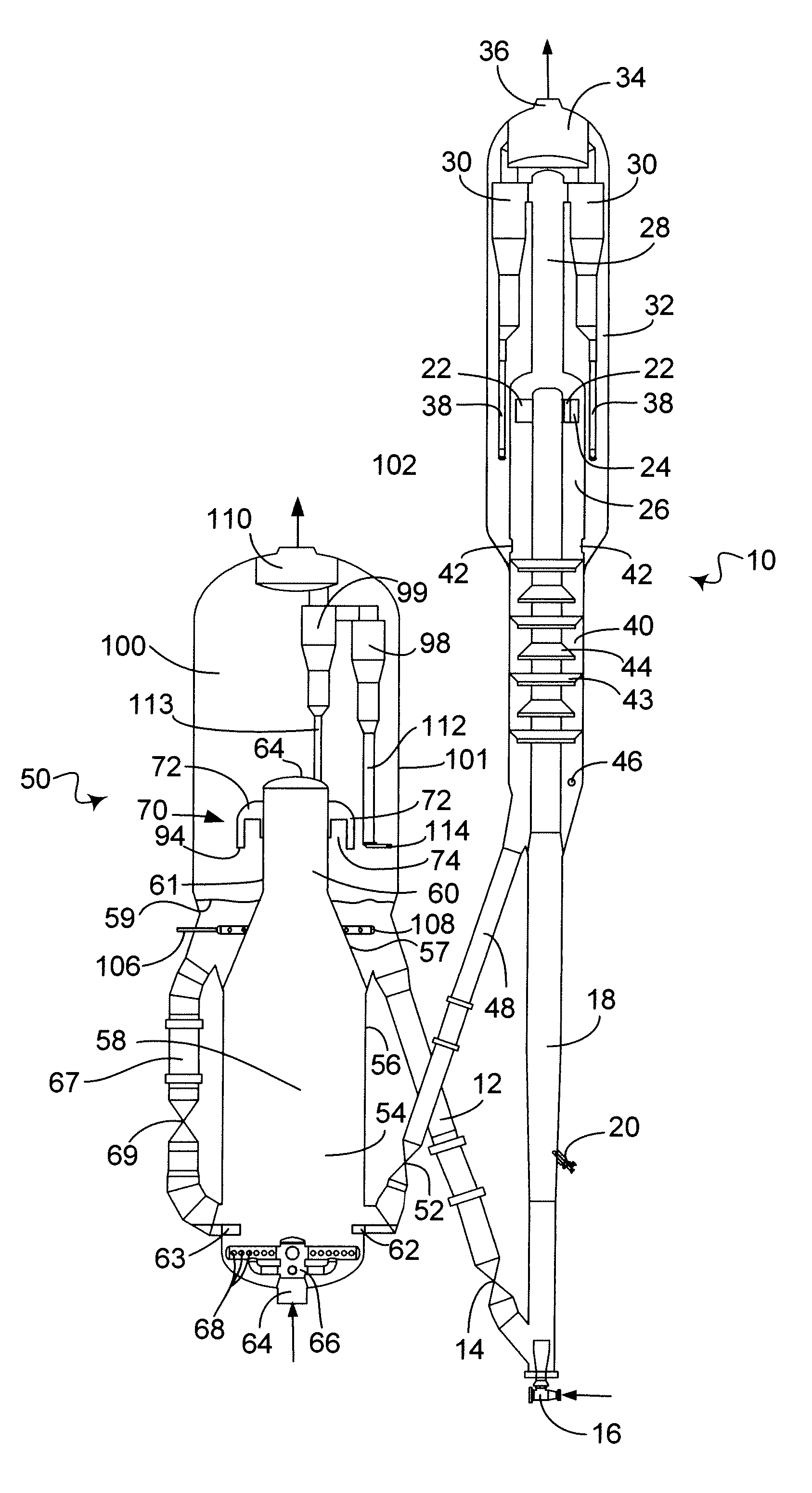
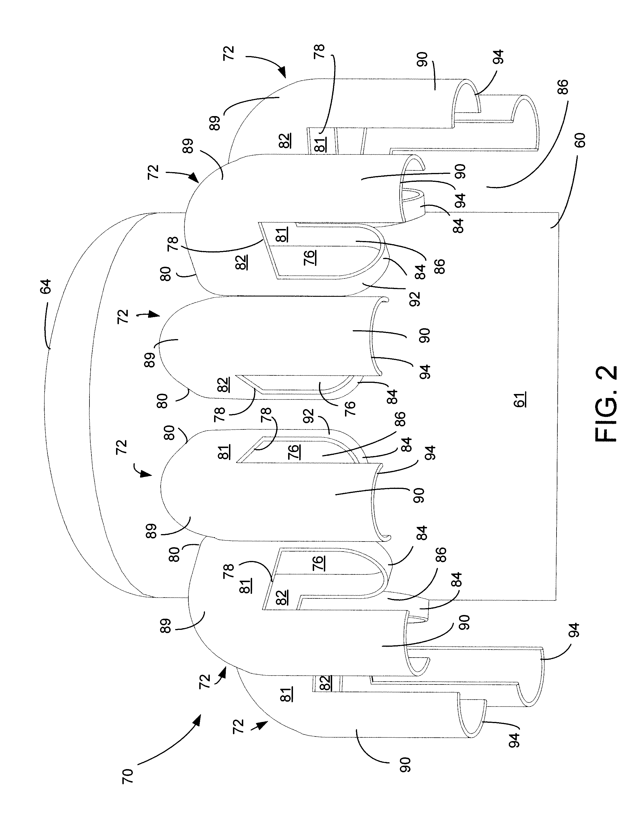
[0017]The process of the present invention may be embodied in an FCC unit. FIG. 1 shows an FCC unit that includes a reactor vessel 10 and a regenerator vessel 50. A regenerator standpipe 12 transfers catalyst from the regenerator vessel 50 at a rate regulated by a slide valve 14 to the reactor vessel 10. A fluidization medium such as steam from a nozzle 16 transports catalyst upwardly through a riser 18 at a relatively high density until a plurality of feed injection nozzles20 (only one is shown) inject feed across the flowing stream of catalyst particles.
[0018]A conventional FCC feedstock or higher boiling hydrocarbon feedstock are suitable feeds. The most common of such conventional feedstocks is a “vacuum gas oil” (VGO), which is typically a hydrocarbon material having a boiling range of from 343 to 552° C. (650 to 1025° F.) prepared by vacuum fractionation of atmospheric residue. Such a fraction is generally low in coke precursors and heavy metal contamination which can serve to...
PUM
| Property | Measurement | Unit |
|---|---|---|
| Flow rate | aaaaa | aaaaa |
| Velocity | aaaaa | aaaaa |
Abstract
Description
Claims
Application Information