Signal extraction circuit

a signal extraction and circuit technology, applied in the field of signal extraction circuits, can solve the problems of difficult to secure stable power supply, reduce the efficiency of rectification, and difficulty in extracting signals, and achieve the effect of stabilizing a voltag

Inactive Publication Date: 2010-09-21
FUJITSU LTD
View PDF9 Cites 19 Cited by
  • Summary
  • Abstract
  • Description
  • Claims
  • Application Information

AI Technical Summary

Problems solved by technology

With regard to the conventional noncontact data carrier, there is a problem in which an attempt to secure a stable power supply voltage makes it difficult to extract a signal.
On the other hand, the turn-on resistance of a rectification element needs to be minimized for effectively securing the power of a power supply and therefore a stable power supply is difficult to be secured if the turn-on resistance of the rectification element is increased by putting an emphasis on the signal detection.
Further, in the case of adopting the configuration of adding an element between the rectification circuit and voltage control circuit for monitoring an electric current as the technique disclosed in the above noted U.S. Pat. No. 6,323,728, a voltage drop corresponding to the added element occurs due to the addition of the current monitor in the power supply path, thus resulting in reducing the efficiency of rectification.

Method used


Image

  • Signal extraction circuit
  • Signal extraction circuit
  • Signal extraction circuit

Examples


Embodiment Construction

[0049]The following is a description of the preferred embodiment of the present invention by referring to the accompanying drawings.

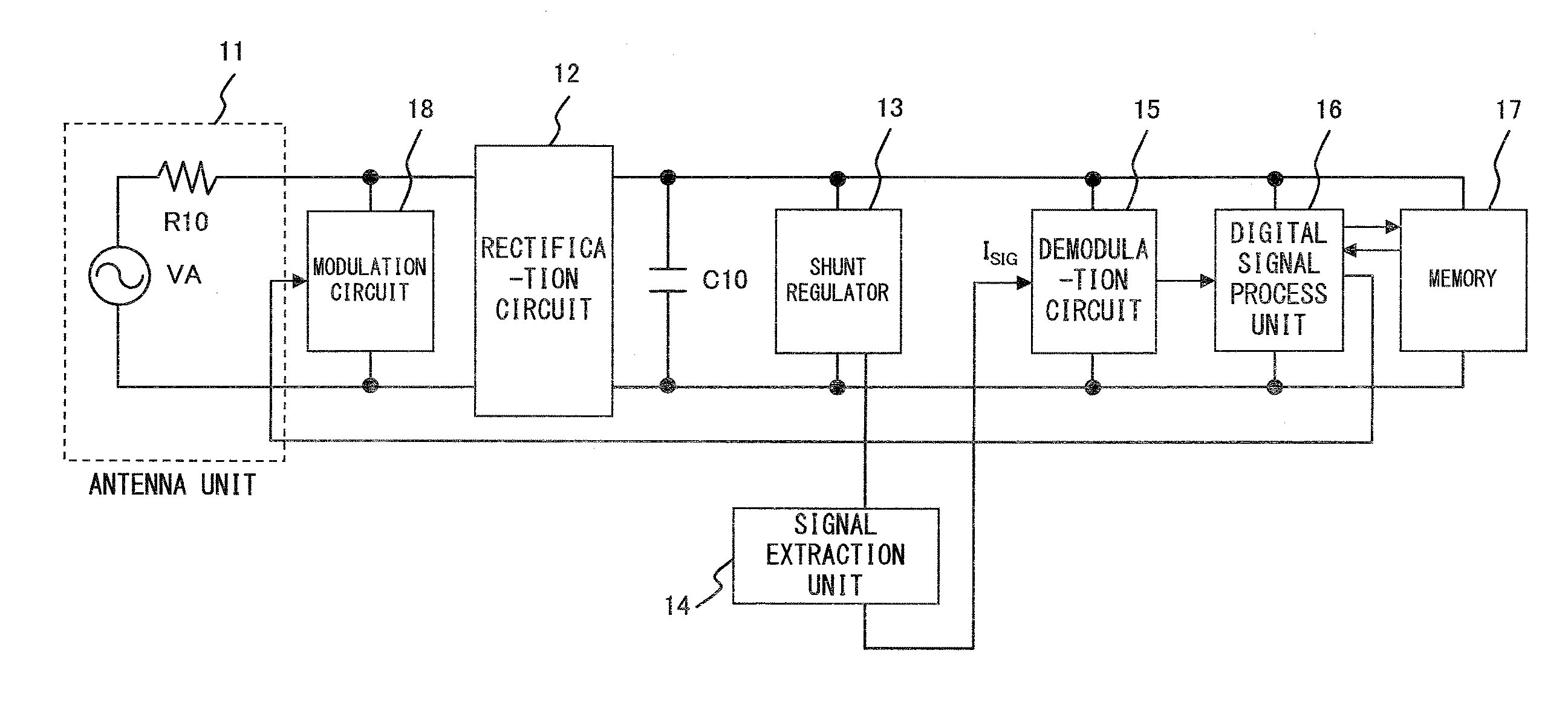
[0050]First is a description of FIG. 3, which is a block diagram showing a first example of the configuration of a radio frequency identification (RFID) tag which is a noncontact data carrier.

[0051]The RFID tag comprises an antenna unit 11, a rectification circuit 12, a capacitor C10, a shunt regulator 13, a signal extraction unit 14, a demodulation circuit 15, a digital signal process unit 16, memory 17 and a modulation circuit 18.

[0052]A reader / writer apparatus emits an electromagnetic wave by feeding to the antenna a radio frequency signal, on which an information signal is superimposed by using an amplitude modulation such as ASK modulation. Having received the electromagnetic wave, the antenna 11, in which a voltage VA is excited, outputs a radio frequency wave superimposed by the information signal. Note that the resistor R10 represents the impeda...


PUM


Abstract

A shunt regulator performs a control so as to stabilize a voltage obtained by rectifying the radio frequency signal output from an antenna unit at a prescribed voltage value. A signal extraction unit extracts the information signal from a bypass current sent by the shunt regulator for the control when the voltage fluctuates.

Description

CROSS REFERENCE TO RELATED APPLICATION[0001]This application is a continuation application of international PCT application No. PCT / JP2005 / 022006 filed on Nov. 30, 2005.BACKGROUND OF THE INVENTION[0002]1. Field of the Invention[0003]The present invention relates to a technique for extracting a signal and in particular to a technique for extracting an information signal from a radio frequency signal on which the information signal is superimposed.[0004]2. Description of the Related Art[0005]A noncontact data carrier, such as a radio frequency identification (RFID) tag and a noncontact integrated circuit (IC) card, does not equip itself with a power supply such as a battery and instead secures the power from the energy of electromagnetic waves, which is emitted by a reader / writer apparatus for access, and performs a data communication by utilizing the electromagnetic waves.[0006]As one example of noncontact data carriers, the RFID tag is described here. FIG. 1 is a block diagram exemp...

Claims


Application Information

Patent Timeline
Patent Type & Authority Patents(United States)
IPC IPC(8): H03D1/10H03D1/04
CPCH04B1/06H03D1/18
Inventor YAMAZAKI, DAISUKE
Owner FUJITSU LTD
Why Eureka
Try Eureka