Traffic communication system

a communication system and communication system technology, applied in the field of communication system variables, can solve the problems of inefficient traffic flow of conventional traffic networks, delays, accidents, and no highly effective means of alerting other drivers, and achieve the effect of improving traffic efficiency and safety, improving communication between vehicles and traffic control devices and/or inter-vehicle communication

Inactive Publication Date: 2005-08-25
AGILENT TECH INC
View PDF7 Cites 207 Cited by
  • Summary
  • Abstract
  • Description
  • Claims
  • Application Information

AI Technical Summary

Benefits of technology

[0011] Embodiments in accordance with the invention are advantageous in that communication between vehicles and traffic control devices and / or inter-vehicle communication is improved. Accordingly, the traffic network communication system improves traffic efficiency and safety.

Problems solved by technology

Such conventional traffic networks are plagued with inefficient traffic flow, delays, and accidents.
For example, there is no highly effective means of alerting other drivers at an intersection of a vehicle that is not yielding to a stop sign or a red light.
As a result, numerous collisions occur at intersections.
Accordingly, the inattentive driver may end-up causing a collision.
One or both drivers may have difficulty in seeing that the other driver adjacent them is changing into the same lane, even if both drivers are using their blinkers.
A collision can be the unfortunate consequence.
Furthermore, such communication means provide limited information.
Hence, drivers do not know how long the light will remain yellow.
Alternatively, a driver may have to brake excessively to stop in time.
Drivers who stop early may end-up being rear-ended by a driver who believes that there is sufficient time to make it through the traffic light and therefore is not expecting the other driver to break.
Similarly, a vehicle (e.g., motorcycle) may be too light or too small to be detected by sensors embedded in the roadway or sensors mounted on light posts.
Hence, the limitations of conventional traffic control systems result in inefficient vehicle traffic flow and inadequate traffic safety.

Method used


Image

  • Traffic communication system
  • Traffic communication system
  • Traffic communication system

Examples


Embodiment Construction

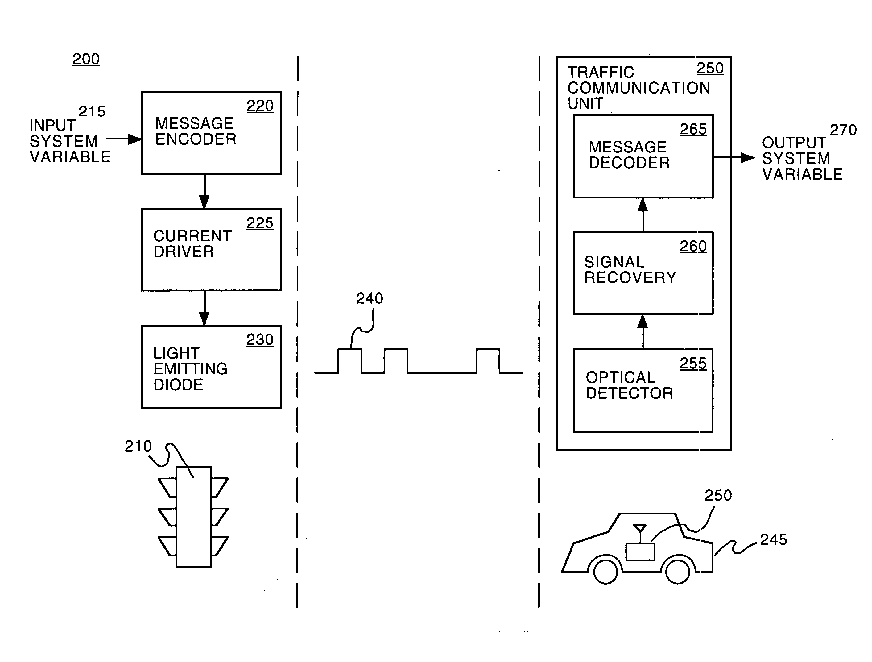
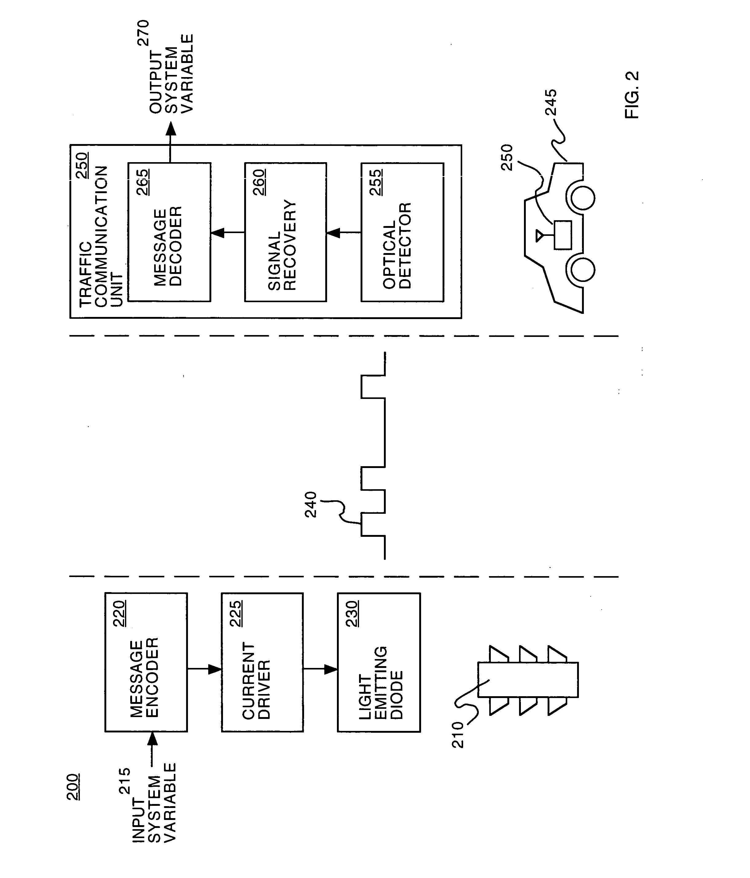
[0020] Reference will now be made in detail to embodiments in accordance with the invention, examples of which are illustrated in the accompanying drawings. While various embodiments in accordance with the invention will be described, it will be understood that they are not intended to limit the invention to these embodiments in accordance with the invention. On the contrary, the invention is intended to cover alternatives, modifications and equivalents, which may be included within the spirit and scope of the invention as defined by the appended claims. Furthermore, in the following detailed description, numerous specific details are set forth in order to provide a thorough understanding of various embodiments in accordance with the invention. However, it is understood that the invention may be practiced without these specific details. In other instances, well-known methods, procedures, components, and circuits have not been described in detail as not to unnecessarily obscure aspec...


PUM


Abstract

Embodiments in accordance with the invention provide communication between vehicles and traffic control devices and/or other vehicles. The communication system provides for communication of system variables such as: signal setting (e.g., red/yellow/green light), signal direction, time to signal change, signal sequence (e.g., next traffic flow), red light runner alert, signal failure, driver urgency, vehicle presence, absolute vehicle location, toll collection information, vehicle speed, roadway condition (e.g., ice on bridge surface), traffic impairments (e.g., delay ahead). The communication system also provides for communication of system variables such as: speed, acceleration/deceleration, braking, lane change with direction, malfunction (e.g., stall). The system communicates utilizing wireless optical, acoustic and/or radio frequency signaling methods.

Description

FIELD OF THE INVENTION [0001] Embodiments in accordance with the invention relate to traffic control systems, and more particularly to a system for communication system variables. BACKGROUND OF THE INVENTION [0002] As depicted in FIG. 1, an exemplary traffic network 100 is shown. The exemplary traffic network 100 includes one or more roadways 110 each having one or more lanes 120, one or more vehicles 130, 140, 160, 170 and one or more traffic control devices 150. Such conventional traffic networks are plagued with inefficient traffic flow, delays, and accidents. The traffic networks are characterized primarily by passive communication means (e.g., red, yellow and green lights) and / or communication means requiring manual operation (e.g., breaking) by the operators of vehicles. [0003] For example, there is no highly effective means of alerting other drivers at an intersection of a vehicle that is not yielding to a stop sign or a red light. As a result, numerous collisions occur at in...

Claims


Application Information

Patent Timeline
Patent Type & Authority Applications(United States)
IPC IPC(8): G06F19/00G08G1/087G08G1/0967G08G1/16
CPCG08G1/087G08G1/096716G08G1/163G08G1/096783G08G1/096791G08G1/096758
Inventor BANEY, DOUGLAS M.
Owner AGILENT TECH INC
Why Eureka
Try Eureka