
Radio frequency process sensing, control, and diagnostics network and system

Active Publication Date: 2018-11-06
CTS CORP ELKHART
View PDF98 Cites 186 Cited by
  • Summary
  • Abstract
  • Description
  • Claims
  • Application Information

AI Technical Summary

Problems solved by technology

By way of background, particulate filter failures are most often caused by malfunctions or failures of other engine or vehicle components upstream of the particulate filter.
Examples of such upstream malfunctions and failures include but are not limited to injector failures, turbocharger failures, coolant leaks, oil leaks, use of incorrect fuels or lubricants, poor engine maintenance, missing or dirty air filters, restricted intake air flow, and the like.
The aforementioned upstream malfunctions may result in excessive soot or particulate matter (PM) loading of the particulate filter, or water, fuel, oil, or coolant collecting on the filter, in one example.
Oftentimes, early-warning signs of these upstream failure modes may not be detected until the problem has become exacerbated to the point where the exhaust particulate filter itself also fails, or its performance Is severely degraded.
Damage to the particulate filter, which could result in particulate matter escaping or passing through the filter, includes cracking of the channel walls, loss of one or more channel end-plugs, or melting of the filter material.
Removal of all or part of the particulate filter from the exhaust system, such as with a straight-pipe or bypass system, also may result in excess PM emissions.
Pressure sensor and model-based approaches for detecting conditions of abnormal filter or system operation suffer from the following deficiencies: pressure measurements lack the resolution to detect failure conditions resulting in PM escaping from the filter at the mandated on-board diagnostic (OBD) limits.
This deficiency has been well-documented in the technical literature, and is the reason why the system is not currently used for OBD; the approach provides only an indirect method of estimating the PM loading level on the filter; differential pressure sensors directly measure the pressure drop across the filter (not the PM loading level), which is confounded by a large number of parameters such as exhaust flow rate, temperature, ash loading levels, soot distribution, filter design, etc.
; the system only functions over a limited range of operating conditions and does not serve as a continuous monitor; pressure-drop measurements are unreliable at low exhaust flow conditions (idle or engine off), during regeneration, during frequent transient operations, and following filter aging once ash has accumulated in the filter; and models (virtual sensors) rely on a known set of operating conditions to accurately estimate filter loading levels; and the systems by definition, do not function well during error conditions or abnormal operation, such as filter malfunctions or failures, as these conditions are outside the capabilities of the models.
Soot sensors suffer from the following deficiencies: soot sensors monitor the soot concentration in a portion of the exhaust gas downstream of the filter and, as a result, the sensors are incapable of monitoring any engine or system malfunctions upstream of the filter and thus incapable of providing advance warning of potential failure conditions; soot sensors do not directly monitor the state of the filter and more specifically only monitor soot in the exhaust downstream of the filter, i.e., the sensor can only provide an indication of a filter failure after the filter has already failed and soot emissions have exceeded the threshold limits; soot sensor accuracy is also affected by exhaust flow velocity, location of the sensing element in the exhaust pipe (as it only samples a small volume of the flow which may not be representative of the total flow), temperature, particle morphology and composition, and accumulation of deposits (ash, catalyst / washcoat particles) as the sensor ages; accumulation type soot sensors do not provide a continuous monitor but rather cycle from a measuring state to a regeneration state and the regeneration state generally requires additional energy input to burn off any accumulated soot on the sensing element; accumulation type soot sensors do not directly monitor the soot particle number or mass in the exhaust stream, but rather the time for sufficient soot to accumulate on the sensing element, thereby providing only an indirect indication of soot levels in the exhaust; soot sensors suffers from poor durability, the accumulation of contaminants (such as ash), as well as thermal shock (water in the exhaust), which limits the sensor life as well as the sensor accuracy over its useful life; and in order to further improve measurement accuracy, many OBD approaches utilizing soot sensors still require predictive models to estimate engine-out soot levels for comparison with the downstream soot sensor measurements.

Method used


Image

  • Radio frequency process sensing, control, and diagnostics network and system
  • Radio frequency process sensing, control, and diagnostics network and system
  • Radio frequency process sensing, control, and diagnostics network and system

Examples


Embodiment Construction

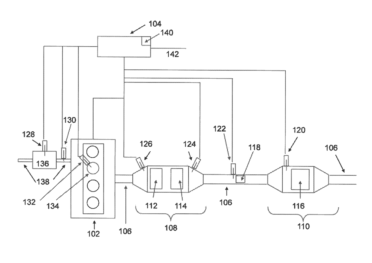
[0036]The present invention is directed to a radio frequency process sensing, control, and diagnostics network and system and, more specifically, to a radio frequency particulate filter system of the type disclosed in United States Patent Application Publication US 2015 / 0358091 A1 and US 2015 / 0355110 A1 published on Dec. 10, 2015, the disclosure and contents of which are incorporated herein by reference in their entirety as though fully set forth herein, and which has been adapted for detecting, sensing, controlling, and diagnosing conditions of abnormal filter or system operation as described in more detail below.

[0037]Specifically, and as disclosed in United States Patent Application Publication US 2015 / 0358091 A1 and US 2015 / 0355110 A1 published on Dec. 10, 2015, the system may be comprised of a particulate filter housed in a conductive enclosure forming a resonant cavity or waveguide; one or more antennas or radio frequency transmitting or receiving probes or sensors configured ...


PUM

PropertyMeasurementUnit
timeaaaaaaaaaa
frequencyaaaaaaaaaa
radio frequencyaaaaaaaaaa

Abstract

A radio frequency sensing, control, and particulate matter diagnostics network and system and method and, more specifically, a radio frequency particulate filter diagnostics system comprising a housing including an inlet connected to a source of particulate matter, a particulate filter in the housing and adapted for filtering the particulate matter, and a radio frequency sensor adapted to detect conditions of abnormal particulate filter or system operation and including at least one radio frequency probe configured to be in contact with the housing for the particulate filter housing and adapted to receive radio frequency signals and a radio frequency control unit in communication with the radio frequency probe.

Description

CROSS-REFERENCE TO RELATED APPLICATIONS[0001]This patent application claims priority and benefit of the filing date of and is a continuation-in-part of U.S. patent application Ser. No. 14 / 733,525 filed on Jun. 8, 2015 and U.S. patent application Ser. No. 14 / 733,486 filed on Jun. 8, 2015, the disclosure and contents of which are expressly incorporated herein in their entireties by reference.[0002]This patent application also claims priority and benefit of the filing date of U.S. Provisional Patent Application Ser. No. 62 / 311,020 filed on Mar. 21, 2016, the disclosure and contents of which is expressly incorporated herein in its entirety by reference.GOVERNMENT SPONSORSHIP[0003]This invention was made with government support under Award No. IIP 1330313 awarded by the National Science Foundation. The government has certain rights in the invention.FIELD OF THE INVENTION[0004]This invention relates generally to a radio frequency process sensing, control, and diagnostics network and syste...

Claims


Application Information

Patent Timeline
Patent Type & Authority Patents(United States)
IPC IPC(8): F01N9/00G01N22/00F01N3/021F01N11/00F01N3/035F01N3/00F01N3/10B01D46/00
CPCB01D46/0086F01N11/00F01N11/005G01N22/00F01N3/021F01N2900/1606B01D2279/30F01N9/002F01N2550/04F01N2550/24F01N2560/12F01N2900/0416F01N2900/0418F01N2900/08F01N2900/1602Y02T10/12Y02T10/40
Inventor SAPPOK, ALEXANDER G.RAGALLER, PAUL A.BROMBERG, LESLIEHERMAN, ANDREW D.
Owner CTS CORP ELKHART
Learn More